

Thank you for your purchase of our Models 2040 USB Interface Circuit Board.
The 2040 supports up to 20 Spring Return Push Button switches and Toggle Switches using a SPDT Configuration.
Have any comments or sugestions, please write us at:
Support@DesktopAviator.com
The 2040 supports up to 20 Spring Return Push Button switches and Toggle Switches using a SPDT Configuration.
Have any comments or sugestions, please write us at:
Support@DesktopAviator.com
Desktop Aviator HOME Page
International Shipping Info
Wiring the 2040
USB Interface Boards
USB Interface Boards

USB Output from the 2040 Board
Installation
Installing the USB Interface requires very little time. All you need is an unused USB Port. Additional Ports can be added to your computer by using a device called a USB Hub. These Hubs can be purchased for as little as $20.00usd on the internet. If you decide have more then 4 devices connected to your computer at the same time, I recommend that you purchase a POWERED USB Hub. This device uses a Wall Transformer to supple power to your interface boards. This prevents excessive power drain on tne computer's Power Supply.
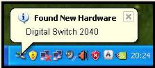
Just plug a USB Cable Series "B" into the jack on the 2040, then into the USB Port on your computer. The computer will sense the Adapter and load the appropriate driver software for its operation. The 2040 will be "seen" as "Digital Switch 2040". That's there is to the installation.
To verify that your computer has accepted the Interface, you can goto the "Game Controller" window. To do this, just cloik on "START" (located in the lower left hand corner of your Windows XP computer's monitor); then click on "Control Panel"; then "Game Controller). Your computer should display the following:
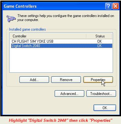
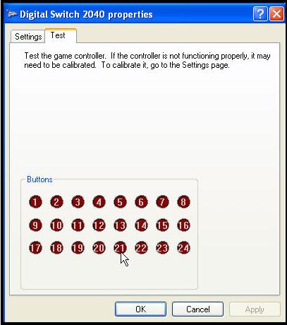
The Properties Window indicates that there are 24 available switch , this is a misconception. There are only 20 Buttons. The extra buttons were included in the USB Program for furtue expansion.
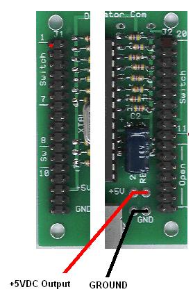
Wiring the Board
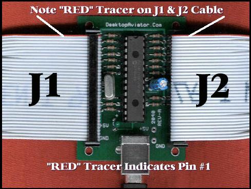
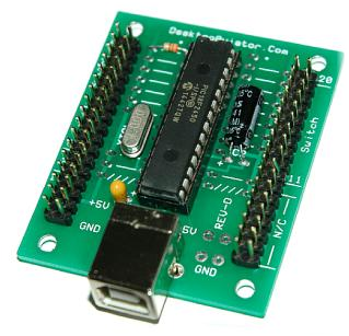
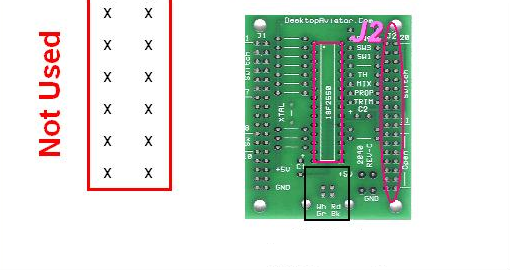
Below is a photo showing the 2040 board and how 17x2 Ribbon Cables can be used to solder the buttons in place on the J1 and J2 Headers. Also shown is the USB Series "B" Cable.
If you wish, you can also use #28 Stranded wire, sodered to the 2-pin Female connectors we supply with your purchase..
If you wish, you can also use #28 Stranded wire, sodered to the 2-pin Female connectors we supply with your purchase..
Below is a YouTube Video we uploaded to show just how the 2040 board is wired to the connector pins.
The Photo seen above shows 2 Ribbon Cables attached to the 2040 board. The cable on the left is designated as J1, while the cable to the right is J2. J1 and J2 are both 17x2 male "Headers" giving you 32 wires for each connector. Note the "RED" tracer on each of the cables, the RED Tracer indicates that the wire with the trace color is Position #1 (wire 1). The second wire down is Position #2; the third wire is Position #3 and so on until wire #34 is reached (last wire).
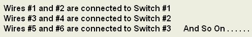
Push Button Switches require only 2 wires to operate. To make wiring of your switches as easy as possible, the 2040 was designed so that 2 adjacent wires are soldered to each switch. In other words, the First (wire with the RED Tracer) and the the Second wire are soldered to a Push Button Switch (switch #1) is all that is needed for your computer to sense the closure of the button. The third and fourth wires are connected to the second button (switch #2). The fifth and sixth wires are soldered to the third Push Button (switch #3). See the pattern?
If Ribbon cables are not available, the switches can be soldered to #28 AWG Stranded wire. Two wires (20 inches max. in length), are soldered to the 2 terminals on the button, while the other ends are soldered to the 2-pin female connectors. When soldered, the 2-pin connectors are placed on two of the horizontal J1 or J2 pins.
If Ribbon cables are not available, the switches can be soldered to #28 AWG Stranded wire. Two wires (20 inches max. in length), are soldered to the 2 terminals on the button, while the other ends are soldered to the 2-pin female connectors. When soldered, the 2-pin connectors are placed on two of the horizontal J1 or J2 pins.
This shorting together of the wires, brings the control pin of J1 and J2 to GROUND. Thus providing a USB output on the appropriate location. It is this USB output that can be SET to any available flight finction that your FSX or even X-Plane supports.
The wire numbers also indicate the Pin Number of both J1 or J2 Connectors (wire #2 is connected to Pin 1 of J1 or J2 - wire #2 is connected to Pin s of J1 or J2 ect).
The wire numbers also indicate the Pin Number of both J1 or J2 Connectors (wire #2 is connected to Pin 1 of J1 or J2 - wire #2 is connected to Pin s of J1 or J2 ect).
Switch Assignments
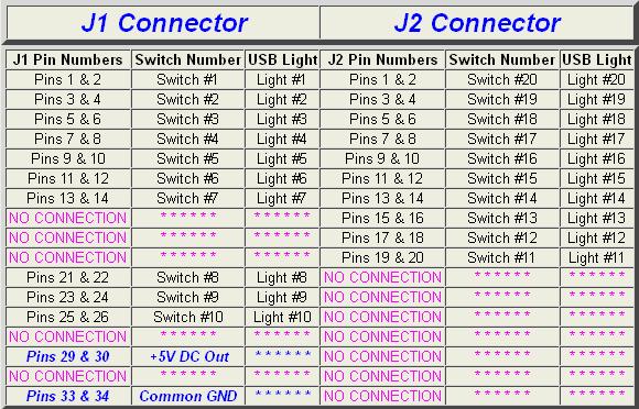
Above is a Table showing J1, J2 Pin Assignments; their functions and what Buttons will light when
the switch is presed (See Digutal Switch 2040 Properties" Window - Above).
Lets go through a few assignments so you fully understand what's happening. With a Robbon
Cable connected to the 2040 J1 Header (or two stranded wires), find the wires connected to Pins 1 & 2 (that is the wire with the RED Tracer and the second down from there). With the "Digital Switch 2040 Properties" window showing, "short" these two wires together. When shorted, the RED Button will light in the window. Remove the short; the light will extinguish. Now short the third and fourth wires on the J1 Ribbon Cable; the #2 RED Button will light. And so on.
The remaining 3 switches (switch #8, switch #9 and switch #10) are connected to Pins 21 ans 22 - Pins 23 and 24 - Pins 25 and 26. The last Digital Switch on the J1 Cable is #10. Pine 29 and 30 and Pins 33 and 34 are Voltahe and Common Ground connections. These pins come in handy if you Switch Design requires voltage to power an integrated circuit, LED, small relay ect. The 5 Volt DC is present on Both Pins 29 and 30 while the Common Grond is connected to Pins 33 and 34.
If your design requires 10 Switches or less, you can stop here. But if you need more then 10, you need to connect a Ribbon Cable to the J2 header and take note of ther required connections from the TABLE seen above.
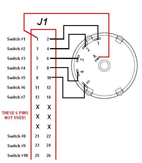
If Pins 1 (RED Tracer) and Pin 2 of the J1 Cable are shorted together, the #20 Button will light. Shorting Pins 3 and 4 will light the #19 button and so on until you reach Pins 21 to 34. These pins are not connected to any circuitry, so they are considered "open" circuits.
the switch is presed (See Digutal Switch 2040 Properties" Window - Above).
Lets go through a few assignments so you fully understand what's happening. With a Robbon
Cable connected to the 2040 J1 Header (or two stranded wires), find the wires connected to Pins 1 & 2 (that is the wire with the RED Tracer and the second down from there). With the "Digital Switch 2040 Properties" window showing, "short" these two wires together. When shorted, the RED Button will light in the window. Remove the short; the light will extinguish. Now short the third and fourth wires on the J1 Ribbon Cable; the #2 RED Button will light. And so on.
The remaining 3 switches (switch #8, switch #9 and switch #10) are connected to Pins 21 ans 22 - Pins 23 and 24 - Pins 25 and 26. The last Digital Switch on the J1 Cable is #10. Pine 29 and 30 and Pins 33 and 34 are Voltahe and Common Ground connections. These pins come in handy if you Switch Design requires voltage to power an integrated circuit, LED, small relay ect. The 5 Volt DC is present on Both Pins 29 and 30 while the Common Grond is connected to Pins 33 and 34.
If your design requires 10 Switches or less, you can stop here. But if you need more then 10, you need to connect a Ribbon Cable to the J2 header and take note of ther required connections from the TABLE seen above.
If Pins 1 (RED Tracer) and Pin 2 of the J1 Cable are shorted together, the #20 Button will light. Shorting Pins 3 and 4 will light the #19 button and so on until you reach Pins 21 to 34. These pins are not connected to any circuitry, so they are considered "open" circuits.
Wiring Push Button Switches to the 2040
Now that you have an understanding on what takes place on the 2040 Interface, lets discuss the
basics on wiring up the Push Buttons. They say that "A picture is worth a thousand words", so here is a diagram that shows you how to wire 20 buttons to the 2040 board.
basics on wiring up the Push Buttons. They say that "A picture is worth a thousand words", so here is a diagram that shows you how to wire 20 buttons to the 2040 board.
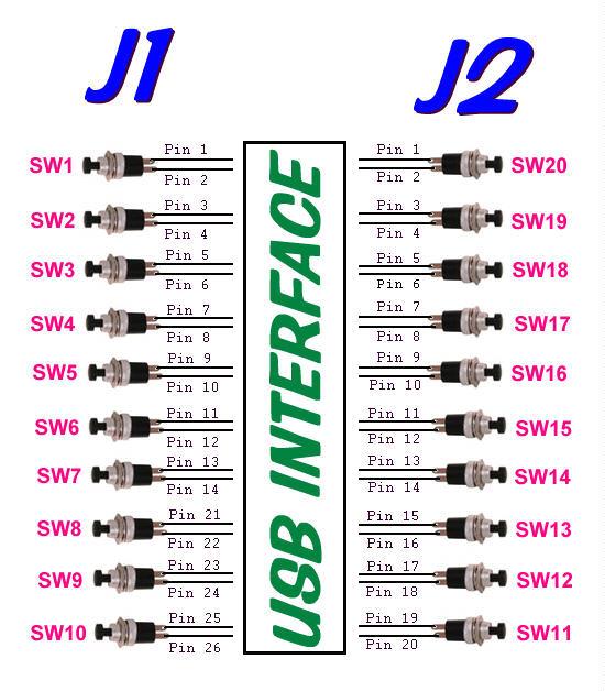
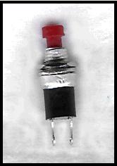
The push button switches are a standard "normally open" spring return type that is available on the Internet or out PARTS Page. The cost ranges from between $0.27 to $0.50 each. Purchase the one that best suite your flight function
The Control Wires from the J1 Header are located at:
Pins 2,4,6,8,10,12,14, then starts up again at: 22,24,26
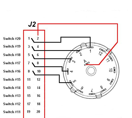
The Control Wires from the J2 Header are located at:
Pins 1,2,5,7,9,11,13,15,17,19
Pins 2,4,6,8,10,12,14, then starts up again at: 22,24,26
The Control Wires from the J2 Header are located at:
Pins 1,2,5,7,9,11,13,15,17,19
Wiring DPDT Switches to the 2040
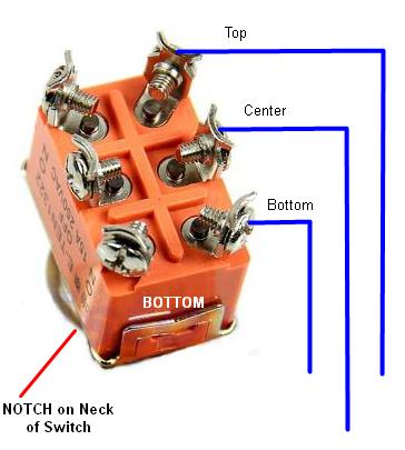
Below is a DPDT Toggle Switch (you can also use SPDT or even a SPST or DPDT Rocker Switch). Of the 6 terminals, we will use only 3 (Top,Center,Bottom)
A
B
C
A
B
C


"B" can also be connected HERE

Just solder a wire from
A to A
B to B
C to C
using the 2-pin connectors that were supplied with your board
A to A
B to B
C to C
using the 2-pin connectors that were supplied with your board
The remaining 2040 inputs can be wired the same
Wiring a second Key Switch to the 2040 Interface
The 2040 board shown less components
Only 5 Terminals are used
Only 5 Terminals are shown
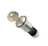
Wiring a 5 Position Key Switch