


Desktop Aviator HOME Page
International Shipping Info


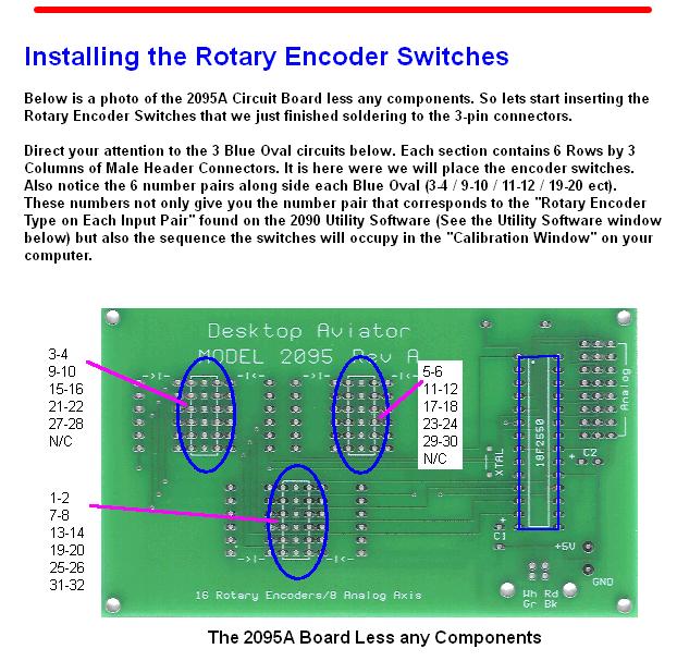
Installation of the Encoder Switches

The software can be downloaded from:
http://www.DesktopAviator.com/Products/Model_2090/encoder.exe
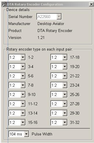
Once downloaded, RUN the Utility Program and you will get a window as seen below:
http://www.DesktopAviator.com/Products/Model_2090/encoder.exe
Once downloaded, RUN the Utility Program and you will get a window as seen below:
With 16 Rotary Encoder Switches connected to the 2095A board, you need to program each encoder using the Utility Program.
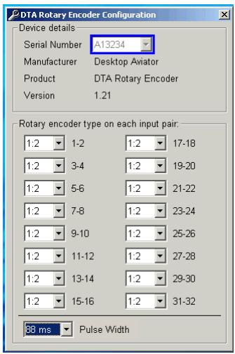
With the 2095A board connected to your computer s USB Port, you will see the board s Serial Number. This number will appear in the "BLUE" box shown to the left. If you have more then one 2095A board connected to your computer, these serial numbers will also appear inside the blue box. Just "click" on the Down Arrow to view.
Notice the "Paired" numbers under the heading "Rotary Encoder Type on Each Pair"; 1-2, 3-4, 5-6, all the way up to 31-32. These numbers correspond to the 3-pin male connection points on the 2095A Board (See Above). You might ask; Why 32? Well, each encoder switch requires 2
connections. One to sense when the switch is rotated to the left and the second, when the switch is rotated to the right. Seeing that the 2095A board accepts 16 encoder switches and each requires 2 connections. That s the reason for 16 pair or 32 connection.
Lets program a switch. Say you have an encoder switch connected to the 2095A board at location 5-6, to program this encoder, you must "set" the "Rotary Pair" 5-6 on the Utility Software window to the suggested settings (1:2). If you have an encoder connected to "Pair" 31-32; you need to "set" the "Rotary Pair" 31-32 in the Utility Software to 1:2. Likewise for the remaining rotary encoder switches you have connected to the board. If you do not have the full 16 encoder switches connected to the 2095A; ALL unused "Rotary Pair" settings MUST be set to "OFF". One good thing about not using the full 16 encoder inputs is that ALL unused "Rotary Pair" can now be used with spring return push buttons. Each "Rotary Pair" input can control Two Push Button Switches. The Rotary Encoder switches we have available on our Parts page also contains a push button feature. When pushing on the shaft of the encoder switch, a small internal switch closes. The switch output on these encoders can also be programmed for additional flight functions. More on that a bit later.
These settings are suggestions but if you get better results on your computer with different settings, by all means, make the changes. Just remember to download and run the 2090 Utility software. Then once programmed with the required number of Encoder Switches, you need not run the software again. It will remain inside your computers memory.
By the way, I did not mention the setting for "Pulse Width". This settings changes the speed of the "pulses" produced by the 2095A board. By changing this setting, you can create short pulses or even long pulses. This setting usually depents on the speed of your computer. The recommended setting for the "Pulse Width" is 96ms.
Wiring the Encoder Push Button Switch
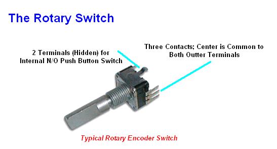
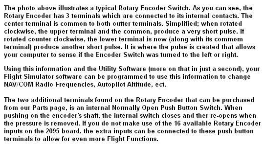
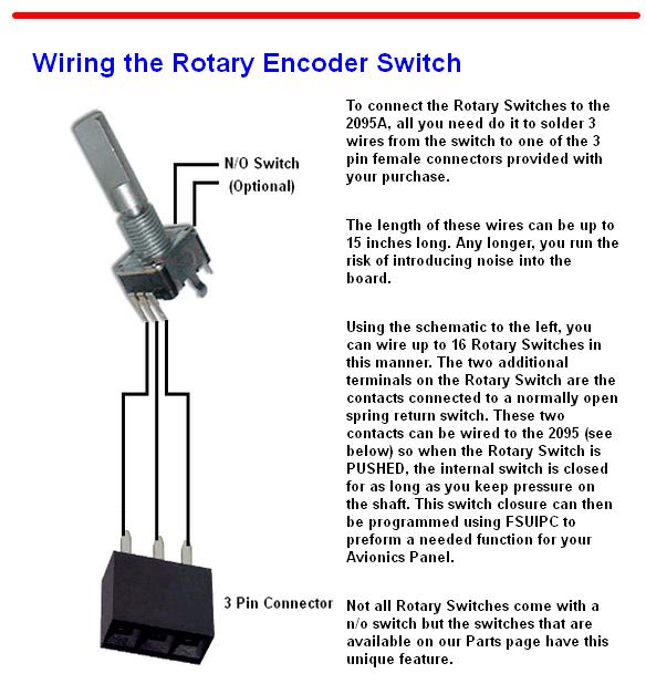
If you are lucky enough to have unused Rotary Encoder inputs, you can make use of them as push button inputs. If you notice, some Flight Sim software allow you to program rotary encoders to change Radio Frequencies, Alt Settings, ADF and alike. Additional Flight Sim features can be achieved by incorporating the internal push button incorporated inside most encoder switches. So with this in mind, lets wire up and program a few encoder inputs to be used as push buttons.
If you are lucky enough to have unused Rotary Encoder inputs, you can make use of them as push button inputs. If you notice, some Flight Sim software allow you to program rotary encoders to change Radio Frequencies, Alt Settings, ADF and alike. Additional Flight Sim features can be achieved by incorporating the internal push button incorporated inside most encoder switches. So with this in mind, lets wire up and program a few encoder inputs to be used as push buttons.
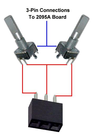
Here we have 2 rotary encoder switches already wired to the 2-pin female connectors as seen above. They too are answ placed onto one of the Rotary Encoder "Pair". If you look at the other side on the encoder switch, you will find another 2 terminals. These terminals are connected to the internal spring return push button switch. It is these 2 terminals which we are interested in.
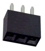
Taking another 3-pin Connector, wire the push button terminals as shown. Two terminals on the encoder switch are common, so they are soldered together and one wire is soldered to the center of the 3-pin connector. The other two terminals are connected to the outter terminals on the 3-pin connector.
Taking another 3-pin Connector, wire the push button terminals as shown. Two terminals on the encoder switch are common, so they are soldered together and one wire is soldered to the center of the 3-pin connector. The other two terminals are connected to the outter terminals on the 3-pin connector.
That s really all there is to it. You can wire up as many puch buttons you need for your panel. Just make sure you have the number of inputs needed.
Adding Rotary & SLIDE Potentiometers
The 2095A Board supports up to 16 Rotary Encoder Switches. But if have unused encoder switch inputs, they can be easily converted to support SPDT and DPDT Toggle and Spring Return Push Button Switches. Below is the wiring of a DPDT and a Push Button Switch to the supplied 3-pin Female Connector that came with the purchase of the board.
Shown is a DPDT Double Pole Double Throw Toggle Switch. SPDT (Single Pole Double Throw) toggle switches can also be used.
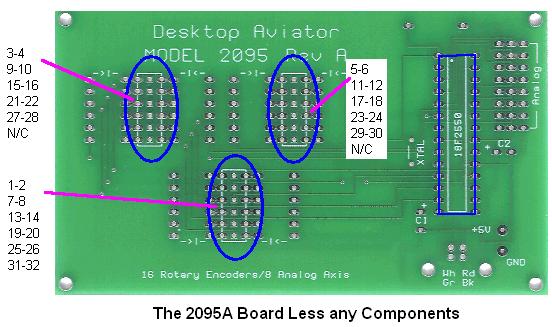
Below is a diagram of the 2095A Board. Note the areas of the board marked with the numbers: 3-4 / 9-10 / 5-6 / 29-30 ect. These Paired numbers correspond to the Input Pairs seen on the 2090 Utility Software program. The program you downloaded (see Above)
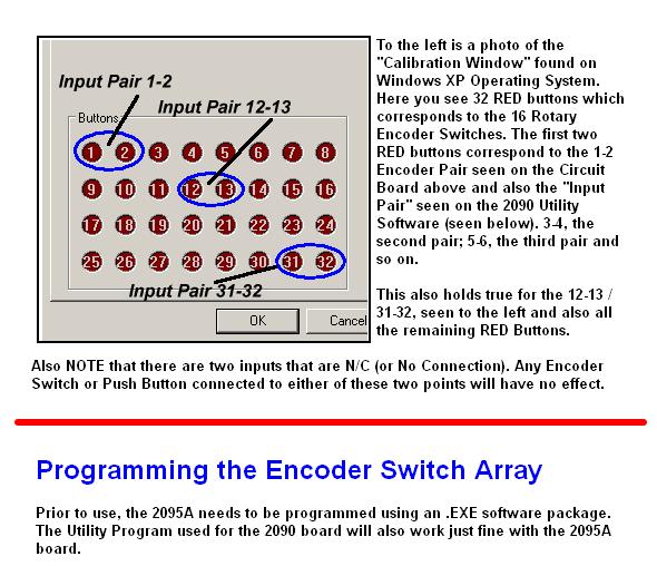
Note the paired numbers 3-4 in RED above. This pair corresponds to the 3-4 seen on the Utility Software Window (see left). The input pair 5-6 in BLUE above, corresponds to the numbered pair 5-6 in the Utility Software Window. And the numbers, 29-30 in GREEN, correspond to the input pair 29-30 on the Utility software Window. See the Pattern?
Say you connect the Toggle Switch you just wired to the paired number 3-4 on the 2095A Board. In order for the board to use this input as a toggle switch input and NOT a Rotary Encoder input, you MUST change the small corresponding window (to the left of the input paired 3-4) to OFF.
Say you connect the Toggle Switch you just wired to the paired number 3-4 on the 2095A Board. In order for the board to use this input as a toggle switch input and NOT a Rotary Encoder input, you MUST change the small corresponding window (to the left of the input paired 3-4) to OFF.
<==
<==
<==
OFF


To do this, just click on the arrow and a smaller window will appear. Using your Mouse, highlight OFF. Then the small window will disappear.
You can then do the same for input pair 5-6 and 29-30 or any other input not being used for a Rotary Encoder Input.
Then remove the board from the USB Port of the computer, then re-insert the board so that the new configuration can be set. You can go into the Calibration Window, look for DTA Rotary Encoder, then click on it. Now, flip the toggle switch and you will see that the appropriate RED Button will light constantly until you flip the toggle switch
Then remove the board from the USB Port of the computer, then re-insert the board so that the new configuration can be set. You can go into the Calibration Window, look for DTA Rotary Encoder, then click on it. Now, flip the toggle switch and you will see that the appropriate RED Button will light constantly until you flip the toggle switch
again The same will hold true, if you connected 2 (or even 1) Push Button to the 2095A. The corresponding RED Button will light up when you press the switch and go OFF when you remove your finger. These RED Buttons can then be set to operate any flight function requiring a Constant ON output from the Board. Setting the 2095A Board to operate with Spring Return Switches is the same as a Toggle Switch.
"Sweet 16" Rotary Encoder
Model 2095A
Wiring & Installation Instructions
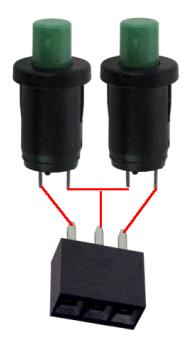

Here, you can wire 2 push button switches to the 3-pin connector. If you need only 1 button, just solder a wire from the common center terminal and a second wire to either end terminal.
Using Two Push Button Switches
Using DPDT Toggle Switch
Wiring a LINEAR Rotary Potentiometer to the Board
The 2095A Board also supports up to 8 Analog inputs. These inputs can be programmed using your Flight Simulator's Settings Window. Along with the 6 standard LINEAR Inputs (Z Rotation, Dial, Slide ect), the board also supports X/Y inputs so as to allow you to build your own Flight Yoke.
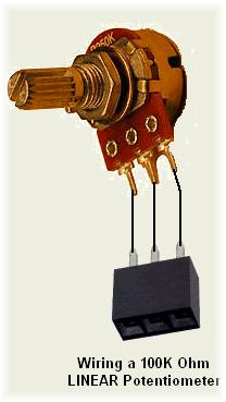
It is recommend that the Value of the Rotary Potentiometer by about 100K Ohms; 10K ohms can also be used but the lower resistance value will allow for more current to be drawn from the computer's USB Port. REMEMBER! to use LINEAR Taper ONLY potentiometers.
To the left is the wiring what will be needed to install potentiometers to the board. The length of the wires can be about 12 to 18 inches. Any longer, shielded cable (microphone cable) wire is recommended.
With all needed potentiometers wired, remove the board from the computer's USB Port and insert the 3-pin connectors to the board. NOTE: the 3x8 male connector pine located to the right side of the board support theanalog input only.
When the potentiometers car connected to the board, reconnect the board to the computer's USB Port. Then using your computer, go into the Windoes Calibration Window. You will then see a BAR Graph for each of the potentiometer connected to the board. Using the Calibration function, each pot must be calibrated to allow the sensing of the full left/right turning of the pot's shaft. Instructions to calibrate the pots are given on each of the calibration windows.
When complete, you can now go into your flight sims SETTINGs Window, or FSUIPC and associate each potentiometer with the desired flight function.
When complete, you can now go into your flight sims SETTINGs Window, or FSUIPC and associate each potentiometer with the desired flight function.
Wiring a LINEAR SLIDE Potentiometer the Board
As with Rotary Potentiometers, the 2095A also supports SLIDE Pots. Should you wish to make your own Push/Pull Throttle quadrant, slide pots are a must.
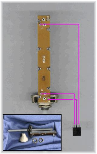
As with the rotary pots, Slide Potentiometers also come is two types; ANALOG and LINEAR. You should purchase LINEAR pots ONLY. Desktop Aviator has 100K Ohm Linear Slide Potentiometers on their PARTS Page.
Wiring a slide is pretty much the same as the rotary but you need to pay attention to the 3 solder lugs located on the bottom. To the left is a photo that shows the needed wiring from the slide pot to the 3-pin female connector. The Wiper Arm Terminal is soldered to the center terminal of the 3 pin connector. The remaining 2 terminals on the pot are soldered to either end of the 3-pin connector. As with the rotary pot, the length of the wired can be about 12 to 18 inches in lenght (the shorter the better). Anything longer, shielded wire is recommended.
When complete, remove the 2095A board from the USB Port. Connect the slide to any of the ANALOG Input terminals on the right side of the board; then reconect. Just like the rotary pot, the Slide Potentiometer will appear in the Calibration Window. Calibration of the Slide can then take place. When calibrated, the slide can then be programmed to controll the appropriate flight function.
Please NOTE: For any Analog Input Bar to appear in the Calibration Window for the 2095A, you MUST have at least one potentiometer connected to the 2095A before plugging the board into your computer s USB Port. When connected, you would need to calibrate the 2095A as per the instructions shown in the Calibration Window.
Please NOTE: For any Analog Input Bar to appear in the Calibration Window for the 2095A, you MUST have at least one potentiometer connected to the 2095A before plugging the board into your computer s USB Port. When connected, you would need to calibrate the 2095A as per the instructions shown in the Calibration Window.
Adding Toggle and Push Button Switches
12-22-2015