

Thank you for your purchase of our Model 2450/B GPS/Monitor.
If you have any comments or need additional information on the use of the 2450/B Panel, please write us at:
Support@DesktopAviator.com
If you have any comments or need additional information on the use of the 2450/B Panel, please write us at:
Support@DesktopAviator.com


Desktop Aviator HOME Page
International Shipping Info
Programming the GPS Monitor Panel
Model 2450 & 2450B
Model 2450 & 2450B
Installation Instructions
To make the installation of the GPS as easy as possible, we have included a full size Template in PDF. This will make it easier to locate the mounting holes and large cut-out area on your flight deck. You can download the Template HERE.
The Model 2450 GPS/Monitor was designed to be flush mounted inside your homemade aircraft panel. The GPS measures 7.25 inches by 5.25 inches.
Four mounting holes are also provided to help in the fastening the GPS to your flightdeck. Seeing that the measurments and mounting hole location is compatible with that of GoFlight panels; the GPS can also be mounted inside GoFlight's
GF-AC Rack.
Once mounted on the GoFlight's Rack or flush mounted inside your flightdeck, take the USB cable coming from the GPS and insert it into an unused USB port on your computer. The computer will automatically sense and load the appropriate driver software. Once loaded, this software will remain on the computer even in the event of a power-down.
ATTENTION! Do not press any of the mini buttons on the small circuit board located on the back of the Model 2450 GPS. It is factory set to the Default settings:
VGA Input and Auto Configuration
Programming the GPS
With the GPS plugged into your computer and the driver software is loaded (Driver Software will automatically be loaded by your computer when the GPS is first plugged in), it's now time to program each Button and Dual Rotary Encoder with the appropriate GPS function. Now would be a good time to let you know that you MUST Keep the GPS Panel connected to the SAME USB port as it is now. If removed and placed into another USB port, all your programming will be lost. So before starting the programming, make sure you are comfortable with the GPS's USB port. If so, lets start programming the Panel.
Programming the GPS with FSX Flight Simulator
When you first run FSX, you will be shown the window seen to the left.
To start Programming the GPS, you need to "CLICK" on the SETTINGS icon as shown.
To start Programming the GPS, you need to "CLICK" on the SETTINGS icon as shown.
You will then encounter the screen to the right.
Locate the "Controls..." icon then "Click"
Locate the "Controls..." icon then "Click"
The next window is where you choose the "Controller Type: Locate
"GPS" then "Click"
To continue programming the GPS, "Click" on
BUTTONS/KEYS
"GPS" then "Click"
To continue programming the GPS, "Click" on
BUTTONS/KEYS
This is the window where all the settings are made. Find Event catagory: And locate GPS/G1000. By using this feature, FSX will eliminate all flight functions NOT used by the GPS. Using the "elevator" located to the right, you can scroll up and down the list. Look for the settings NOT associated with the G1000 Series GPS. This is the listing where we will start the programming of the Series 500 GPS Panel. Highlight the Function: GPS CLR button (activate); then "Click"
When highlighted, "Click" New Assignment near the bottom of the window.
A new window will pop-up inside the main window. Now the fun begins. On the GPS photo seen above (the one with all the numbers on it), find the CLS button
(#5) and press. Button 5 will appear in the New Assignments window. When seen, "Click" on OK. CLS is now programmed into FSX.
(#5) and press. Button 5 will appear in the New Assignments window. When seen, "Click" on OK. CLS is now programmed into FSX.
When you "Click" OK on the New Assignments window, you are brought back to the main Settings page. Note that GPS CLR button (activate) has been assigned the #5 button.
Also note the Repeat Bar. It must remain all the way to the LEFT as seen. The Repeat Bar is to be at its left position for ALL GPS functions.
Now using the same procedure as described, you can now program the remaining buttons to the selected functions. Below are the additional settings:
Also note the Repeat Bar. It must remain all the way to the LEFT as seen. The Repeat Bar is to be at its left position for ALL GPS functions.
Now using the same procedure as described, you can now program the remaining buttons to the selected functions. Below are the additional settings:
USB #17 and #18 are located on the OUTTER Knob of the Dual Rotay Switch. Instead of pressing a button, here you turn the knob either to the left (#17) or to the right (#18)
USB #19 and #20 are located on the INNER Knob of the Dual Rotary Switch. This time, turning the inner knob to the left will create USB #19 and to the right; USB #20)
USB #14 is generated by pushing down on the inner knob.
USB #19 and #20 are located on the INNER Knob of the Dual Rotary Switch. This time, turning the inner knob to the left will create USB #19 and to the right; USB #20)
USB #14 is generated by pushing down on the inner knob.
Programming the GPS with FS-2004
Your GPS Panel Buttons can also be programmed with the available functions provided with your FS-2004 Flight Simulator. Seeing that the programming procedure is almost identical to that of FSX, I will not cover the programming here. The FS2004 GPS settings are the same as seen on FSX, just the graphic screen has changed a bit.
How to Use a Garmin Series 500 GPS
To Purchase the Model 2450 GPS Panel, Click HERE!

Installing the GPS Monitor

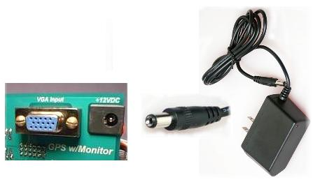
Optional Wall Transformer
Power Plug
Take the Power Plug from the Wall Transformer
and place it into the +12VDC receptacle on the GPS
circuit board.
and place it into the +12VDC receptacle on the GPS
circuit board.
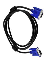
VGA Cable - Supplied with GPS
Connect one side of the VGA Cable to the VGA Input connector on the GPS circuit board.
The other side of the VGA Cable should now be connected to the secondary VGA Output receptacle on the back of your computer. This connector can be found on the Video Card.
The other side of the VGA Cable should now be connected to the secondary VGA Output receptacle on the back of your computer. This connector can be found on the Video Card.
With the Wall Transformer connected to the GPS Board, the Monitor will be ON showing a BLUE Screen.
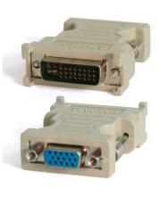
Should your Video Card have only DVI outputs, you can purchase a DVI to VGA Adapter as seen to the left. This adapter will allow the GPS' VGA input to be used with DVI connectors. A Google Search finds many Adapters in all price ranges.
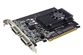
A typical Hi-Tech Video Card (with 1Meg+ video memory) that supports 1 HDMI and 2 DVI outputs
Installing 2 Monitors to your Flight Sim
As soon as the 2450 hit the market, we have had a number of emails asking "How to Add the GPS to my Flight Sim setup". Well; It's a relatively easy task. We've found these videos on Youtube from Roger Dodger. This 2 Part Video series explains in plain language the computer requirements and what is needed to extend the graphics onto a second monitor.......
... In this case, the second monitor is the 2450. So sit back and take a few minutes to watch these videos. They will help you in the installation of your new GPS.
Boy, we sure did cover a lot of ground, but now that you have a working GPS for your Flightdeck, "How do you use it"? Well, a detailed explanation on the proper use of a GPS is beyond the scope of this site, so I did one better. I found a well produced 3 part series on Youtube. So sit back and enjoy . . .
". . . Flying the GPS with Ease"
". . . Flying the GPS with Ease"
Installing 3 Monitors to Your Computer
Another handy device is the DVI to VGA Cable. With this cable you will be able to connect the GPS/Monitor to a Video Card that uses of a DVI Output.

NOTE: Desktop Aviator will not be held responsible for any damage to the GPS/Monitor due to using a Power Supply delivering the incorrect Voltage (in excess of 12VDC) or any damage created by a Power Supply of the Wrong Polarity. Positive; Center Terminal. GROUND; Outside Terminal. ONLY!
For some Helpful ideas on Undocking and setting-up the Monitor, goto:
AVSIM Flight Simulator Forum
For First Time visitors, Registration is Required!
AVSIM Flight Simulator Forum
For First Time visitors, Registration is Required!
NOTE: The only difference between
the 2450 and 2450B is that the 2450's "Display On/Off" button was removed and was replaced with a Power On/Off Toggle Switch. Otherwise, all programming instructions are the same for BOTH Models.
the 2450 and 2450B is that the 2450's "Display On/Off" button was removed and was replaced with a Power On/Off Toggle Switch. Otherwise, all programming instructions are the same for BOTH Models.
Not Available
on the 2450B =====>
on the 2450B =====>
On the 2450B - This
Button was replaced
with a Power On/Off
Switch ==========>
Button was replaced
with a Power On/Off
Switch ==========>
Adjusting for Contrast, Brightness ect
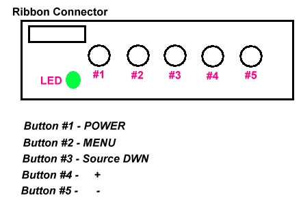
On the back of the GPS Panel is a small circuit board mounted to the mother board. It has a bi-colored LED, 5 mini-push buttons and a white ribbon cable attached to it.
To the right is a drawing of the board. Button #1 controls the power going to the monitor. When there is no power, the LED is RED in color; when power is applied, the LED is GREEN. Button #2, when pressed displays a number of on screen choices that allows for monitor settings and configurations. Button #3 allows for the downard scrolling of the available settings shown on the menu window. Button #4 and #5 alows you to increase or decrease
To the right is a drawing of the board. Button #1 controls the power going to the monitor. When there is no power, the LED is RED in color; when power is applied, the LED is GREEN. Button #2, when pressed displays a number of on screen choices that allows for monitor settings and configurations. Button #3 allows for the downard scrolling of the available settings shown on the menu window. Button #4 and #5 alows you to increase or decrease
the brightness and contrast levels of the screen. A Bar Graph shows the level of Adjustments by it left
and right movements. All adjustments are made when the LED is GREEN.
and right movements. All adjustments are made when the LED is GREEN.

Links to aviation directory
resources & information websites
Adjusting Video Input
The Video Monitor used with the GPS supports 2 video inputs; AV and VGA. For the proper operation of the GPS, the selected input MUST be VGA. With the montior conected to the VGA (or DVI - using an adapter), press the
#3 button on thesmall circuit board. In the upper right hand corner, you will see the video setting. It will be showing
either AV or by pressing the #3 button again, a BLUE screen will be seen and the Text NO SYNC is seen. The
No Sync text will be seen when no video is present on the supplied VGA cable. Also note, what the LED will be in RED indicating that no video is detected.
So, if your monitor shows a Blue screen with AV on the upper right corner, pres the #3 button once to configure the
monitor for VGA use.
Adjusting Video Horizontal Flip
The circuit board Driving the Monitor also supports a Horizontal Flip feature. For the proper orentation on the monitor's video content, you can adjust this setting by pressing the #2 button THREE Times. On the third press, the monitor will display the TEXT "DOWN". With "Down" showing; press the #5 button and notice how the video flips with each press. With the proper video orientation seen, press the #2 button THREE times to flip through the menue until the menue is removed.
Adjusting Video Card
The GPS does require a Video Card capable of supporting multipal monitors. With newer video cards, driver software is also provided. With the purchase of your GPS, we provided you with a VGA Cable. This cable can be connected directly to a VGA output on the video card. If not available, a VGA to DVI -I Dual Link Adapter can be used to connect the GPS to a DVI output on the card. Either way will work just fine.
Now, with the GPS connected to the video Card and the VGA Cable connecting the GPS to the video card, apply power to the the panel by turning the on/off switch (lower left side of the panel) to the right. The BLUE screen should be present with the TEXT "NO SYNC". At this time, no video is seen on the monitor. This does not mean that the panel is defective. You need to tell the video card that the monitor is connected. Seeing that there are many video cards on the market, I can not describe, in detail, how to configure each. So here is an overview.
With the video card driver software seen on the computer screen, locate the file that tells the card that another video monitor is connected and that is should recognize it. Also, you need to configure the software as to use the GPS as an EXTENDER monitor. This will allow you to Undock the GPS screen seen on the computer's main monitor running FSX and bring it into the GPS screen. Resizing of the undocked screen probably will need to be made so that the undocked screen can fill the entire monitor.

Flight Simulator LINKS


Updated 7-6-2016