

Thank you for your purchase of our Model 2570 LED Toggle Switch Controller.
If you have any comments or need additional information on the use of the
2570 Panel, please write us at:
Support@DesktopAviator.com
If you have any comments or need additional information on the use of the
2570 Panel, please write us at:
Support@DesktopAviator.com
Desktop Aviator HOME Page
International Shipping Info

Wiring the Model 2570 to Toggle/Rocker Switches with
Internal LED
Internal LED

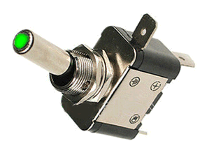
New from China is a standard size Toggle Switch (or Rocker/Paddle switch) with a built-in LED. The LED can be powered with 5 to 12VDC. Even if the switch indicated the need of 12Volts, the 5VDC delivered from your computer's USB Port can also be used without any noticable difference in brilliance.
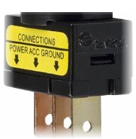
The LED switches can be distinguished from standard switches by the designations on the 3 terminals located on the back of the switch. The LED Switch Terminals are marked POWER - ACC - GROUND.
The POWER Terminal requires either 5 or 12VDC
The GROUND Terminal is your common Ground connection
And the ACC is the controlled output that is connected to the 2570 board.
But seeing that the 2570 requires a 5VDC input, I will make reference to the 5V from now on throughout this instruction page.
When properly connected to the 2570, the LED is OFF when the toggle handle is Down. When flipped UP, two things happen; first the LED lights and the 2570 creates a 1/4 second pulse at the USB Port. When the togle switch is Flipped OFF, the LED extinguishes and the 2570 creates another 1/4 second pulse at the same USB Output. The output pulse is similiar to our Model 2120 board and can be programmed the same way.
The 2570 supports Flight Sim settings as:
LANDING_LIGHTS_TOGGLE or
LANDING_LIGHTS_on/off
Notice the wording TOGGLE and On/Off. This text lets you know that the flight sim requires 1 pulse to turn a flight function ON and another pulse to turn the same function OFF.
Wiring
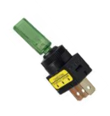
Here is a closeup of the LED Togle Switch. You can plainly see the POWER - ACC - and the GROUND Terminals. To make the wiring of the 2570 as painles as possible we designed the 2570 board with 31 groups of 3 pins each. This makes the 2570 100% compatible with our 12 and 20 inch 3-Pin Extension Cables. These cables can be seen on our PARTS Page.
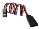
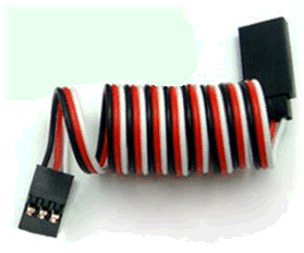
The Extension Cables have 3 colored coded wires; RED, BLACK and WHITE. If we take one of the Extension cables and cut off the MALE connector (the larger of the two connectors), we can solder the wires directly to the LED Toggle as:
RED wire to the LED Toggle Switch Terminal POWER
BLACK wire to the LED Toggle Switch Terminal GROUND
WHITE wire to the LED Toggle Switch Terminal ACC
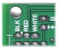
With this wire complete, you now have a switch assembly. This assembly is now plugged into any of the 31 inputs on the 2570 board. This is a polarity sensitive connection, so we've included
on the face of the circuit board, TEXT to indicate the wire color that is needed to be inserted at each of the horizontal pins.
(See Below). Just insert the Extension onto the board so that the color of the cable wire matches the written color on the board.
The Extension Cables have 3 colored coded wires; RED, BLACK and WHITE. If we take one of the Extension cables and cut off the MALE connector (the larger of the two connectors), we can solder the wires directly to the LED Toggle as:
RED wire to the LED Toggle Switch Terminal POWER
BLACK wire to the LED Toggle Switch Terminal GROUND
WHITE wire to the LED Toggle Switch Terminal ACC
With this wire complete, you now have a switch assembly. This assembly is now plugged into any of the 31 inputs on the 2570 board. This is a polarity sensitive connection, so we've included
on the face of the circuit board, TEXT to indicate the wire color that is needed to be inserted at each of the horizontal pins.
(See Below). Just insert the Extension onto the board so that the color of the cable wire matches the written color on the board.
Here is the 3-Pin Extension Cables that can be found on our Parts Page.
This is the side that can be cut!
J1
J2
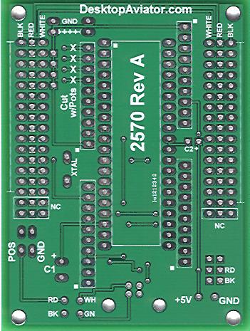
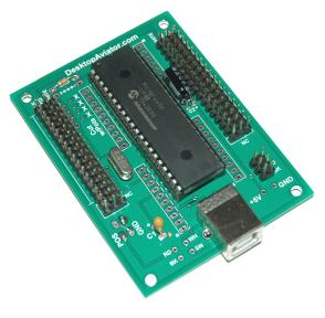
To the left is a photo of the 2570 circuit board (less components).
Switches numbered from 1 to 15 can be connected to the J1 male header connector, while Switches numbered from 16 to 31 can be plugged intp the J2 male header connector.
Note that there are 3 header connections that are marked NC (No Connection).
That's it for the wiring of the 2570 board. Now just plug the board into an unused USB Port. If this is the first time the board was plugged in, your compuer will automaticall load the needed driver software. This IS truely
Plug-n-Play operation!
Switch #1
Switch #15
Switch #16
Switch #31
When the driver software is loaded, go into your Calibration Window and highlight the "Model 2570" seen in the small window. You should now see 31 small RED Buttons. Flip each Toggle Switch into the UP position. You will see two things; first, the LED will Light and second, you will see a 1/4 second pulse on the RED Button that corresponds to the toggle Switch you just flipped up. Now, flip the toggle switch DOWN. Again, you will see two operations. The first is that the LED is now turned OFF and that a second 1/4 second pulse is created by the 2570 board.
Do this test for the remaining 30 toggle switches. It is now time to run your Flight Simulator and program each toggle switch to the needed Flight Function.
Do this test for the remaining 30 toggle switches. It is now time to run your Flight Simulator and program each toggle switch to the needed Flight Function.
Addium - 10-28-2013
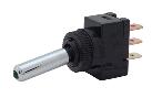
Wiring Instructions for our NEW LED Tipped Toggle Switch.
These Toggle Switches can be purchased from our PARTS Page
These Toggle Switches can be purchased from our PARTS Page
Solder this
Terminal
to the BLACK
wire on the Extension Cable
Terminal
to the BLACK
wire on the Extension Cable


12in or 20in 3-Wire
Extension Cable
Extension Cable
When soldered, place the extension Cable into either the J1 or J2 Header connectors as shown above.
Solder this Terminal
to the RED wire on the Extension Cable
to the RED wire on the Extension Cable
Solder this Terminal
to the WHITE wire on the Extension Cable
to the WHITE wire on the Extension Cable
This is the Male connector of the Extension Cable. This connector can be cut off and the 3 wires soldered to the LED Toggle Switch as seen to the right.
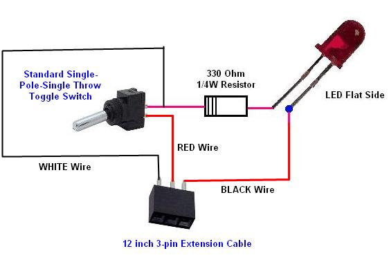
Wiring a SPST Non-LED Tipped Toggle Switch to the 2570
with External LED Light
with External LED Light
Addium 7-29-2016
Attention International Customers
If you live outside of the U.S. & Canada and wish to purchase this item: Please email us your complete shipping address. We will be more then happy to email you the required shipping Fees.
Any Over Payments are Quickly REFUNDED via PayPal.
For International Sales, Please read the
Terms & Conditions for Worldwide Shipping
Click Here to eMail us:
DesktopAviator@USA.com
Addium - 12-28-2016
The 2570 also supports Standard SPST Toggle Switches without LEDs. Just solder the WHITE and RED extension cable wires to the Switch. The BLACK is not used. Either cutoff or tape to prevent any shorts.