

Thank you for your purchase of our Model 2060 DP3T Emulator Board.
Below we will discuss the Wiring and Requirements for your NEW Board.
Have any comments or sugestions, please write us at:
Support@DesktopAviator.com
Below we will discuss the Wiring and Requirements for your NEW Board.
Have any comments or sugestions, please write us at:
Support@DesktopAviator.com

Desktop Aviator HOME Page
International Shipping Info
Wiring the 2630 DP3T Emulator Board

The Model 2630, was designed to give the builder an easier way to connect the switches using a 3-pin extention cable. Just cut-off the "male" connector of the cable and solder the switches as seen below. Then just place the "female"side of the cable into any of the available J1 and J2 input pins. One 3-pin cable can be used to wire-up either ONE SPDT or one DPDT Toggle or Rocker Switch. The Extension cables comes in 2 sizes; 12 inches and 20 inches. Both types have a Male and Female connector so by mating the M/F connectors together, you can easily lengthen the cables. These cables can be found on our PARTS Page.
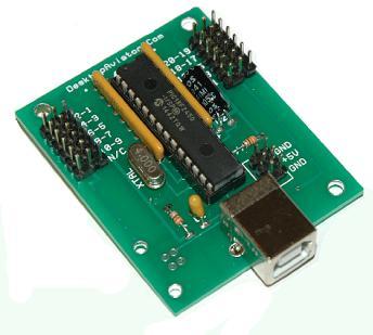
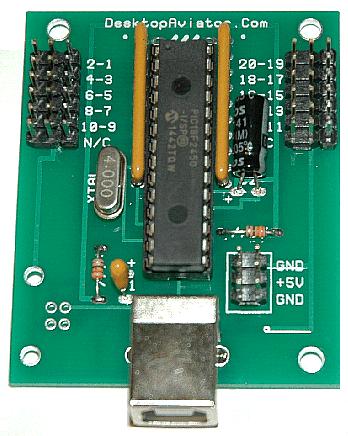
Board Layout
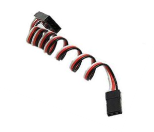
3-Pin Extension Cables


Flight Simulator LINKS

Also note that we also included a 2 x 3 connector that provides USB Power. This +5VDC can be used to power reed relays, LED indicator lights or any other small devices. Devices that draw a large amount of current can not be connected to the USB as it might cause harm to your computer's Power Supply.
Also note that the colors on the Extension Cable corresponds to the polarity of the 2 x 3 connector. The center wire on the Extension cable is red. This is the COMMON Ground connection. The outer wire is colored BLACK which corresponts to one of the 2630 inputs. The WHITE wire corresponds to the another 2630 input pin.
Also note that the colors on the Extension Cable corresponds to the polarity of the 2 x 3 connector. The center wire on the Extension cable is red. This is the COMMON Ground connection. The outer wire is colored BLACK which corresponts to one of the 2630 inputs. The WHITE wire corresponds to the another 2630 input pin.
Switch wiring for the 2630 Board
The 2630 Board creates a CONSTANT ON Output at each of its 30 USB Outputs. This output depends on the position of the DPDT Switches. Should you elect to take full advantage on the 2630's capabilities, you need to wire 10 DPDT or SPDT switches as seen above.
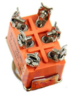
Take either the 12 or 20 inch Extension Cable (These cables can be purchased from our PARTS Page) and cut off the MALE Connector (the Larger of the 2 connectors on the cable) and solder the WHITE wire to the TOP Terminal on the Switch. Solder the RED wire to the Center Terminal and the BLACK Wire to the Bottom Terminal. When complete, the cable can be connected to any of the available inputs on the 2630 board's input: 1-2, 3-4, 5-6, 7-8, 9-10 (with the WHITE wire facing the computer chip) on the J1 Side and 11-12, 13-24, 15-16, 17-18 or 19-20 (with the WHITE wire facing to the edge of the board) on the J2 side. When connected to the USB Port on your computer (as seen on the Calibration Window), flip the toggle switch to all 3 positions; each will produce a CONSTANT ON (RED Button) at the USB output corresponding to the input pins the switch was connected to.
Take either the 12 or 20 inch Extension Cable (These cables can be purchased from our PARTS Page) and cut off the MALE Connector (the Larger of the 2 connectors on the cable) and solder the WHITE wire to the TOP Terminal on the Switch. Solder the RED wire to the Center Terminal and the BLACK Wire to the Bottom Terminal. When complete, the cable can be connected to any of the available inputs on the 2630 board's input: 1-2, 3-4, 5-6, 7-8, 9-10 (with the WHITE wire facing the computer chip) on the J1 Side and 11-12, 13-24, 15-16, 17-18 or 19-20 (with the WHITE wire facing to the edge of the board) on the J2 side. When connected to the USB Port on your computer (as seen on the Calibration Window), flip the toggle switch to all 3 positions; each will produce a CONSTANT ON (RED Button) at the USB output corresponding to the input pins the switch was connected to.
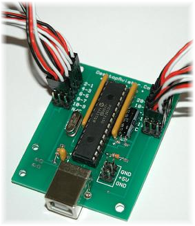
Below is the layout for the 2630 board. Unlike our Model 2120 (and equivalents) that has a J1 and J2 connector configured as a 17 x 2 input, "The Board" have Two 3 x 6 input pins for both J1 and J2 inputs. This allows each 1 x 3 inputs to have TWO switch terminals connected using just 1 Extension Cable. The 2630 supports up to 10 switches, so as you can see the last of the 3 x 6 row of pins for both J1 and J2 are open pins so no connections can be made here (N/C see below). The CENTER Row of the J1 and J2 are the COMMON connections for ALL switches connected. Whereas the pins to the left and right of center are the CONTROL Inputs to the board.
J1
J2


Common Ground
Common Ground

First 5 Switches
Connected HERE
Connected HERE
Second 5 Switches
Connected HERE
Connected HERE
To Series "B" USB Cable
+5VDC for LED
Connections
using DPDT Switch
Connections
using DPDT Switch


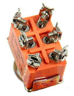
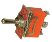
Double Pole - Double Throw (DPDT) Toggle Switch with Center OFF Position.
3-Pin Extension Cable 12 or 20 inches in length
Cut off the MALE Connector and solder it to the switch

FEMALE Connector to 2630 Board J1/J2


BOTTOM
Solder this side to the
WHITE wire on the
Extension Cable
WHITE wire on the
Extension Cable
Top
Center
Bottom
Solder this side to the
WHITE wire on the
Extension Cable
WHITE wire on the
Extension Cable
Solder this side to the
RED wire on the
Extension Cable
RED wire on the
Extension Cable
Solder this side to the
BLACK wire on the
Extension Cable
BLACK wire on the
Extension Cable
NOTCH on Neck of Switch

Adding an LED to the Switch
RED wire already soldered HERE. This is the Common Ground point


Add this JUMPER wire.

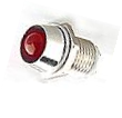

LED Indicator Lights
6VDC (Red/Green)
6VDC (Red/Green)


To 5VDC terminal
on 2630 Board
on 2630 Board
WHITE wire already
soldered HERE.
soldered HERE.
BLACK wire already soldered HERE.
Connections to the 2630 Board (J1 or J2)
Seeing that we are using a DPDT switch and the first set of 3 terminals are already connected to the Extension cable (connected to the 2630 board), we can easily add 2 LED lights as switch position indicators to the remaining 3 terminals.
RED wire already soldered HERE. This is the Common Ground point


Add this JUMPER wire.

WHITE wire already
soldered HERE.
soldered HERE.
BLACK wire already soldered HERE.
Connections to the 2630 Board (J1 or J2)

LED Lights
NEEDS 330 ohm Resistors
NEEDS 330 ohm Resistors
To 5VDC terminal
on 2630 Board
on 2630 Board


2 x 330 ohm Resistors 1/4W or 1/8W
SHORT Lead on LED
SHORT Lead on LED
REMEMBER: LEDs are Polarity Sensitive.
SHORT Lead goto BLACK wire - LONG
Lead goes to +5VDC
SHORT Lead goto BLACK wire - LONG
Lead goes to +5VDC
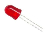
Above, we are using a RED and a GREEN LED Indicator rated at 6VDC. You can also use an LED rated for 12VDC. You will not see any difference in the brightness of the light. NOTE: WE are using LED Indicators; these devices already have a 330 ohm resistor installed inside the device. This resistor prevents the Indicator from drawing excessive current from the 2630 board and thus blowing out the LED. Stand alone LEDs can also be used in place of the Indicators but you need to install the two 330 ohm resistors yourself; one for each LED. This can be seen Here.
Rocker Switches, whether they are SPDT or DPDT are wired the same as the Toggle Switch see above. LEDs can also be wired to DPDT Rocker as well.
The Completed 2630 Board
With all the switches soldered and connected to the 2630 board, this is what it should look like.
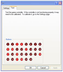
With the 2630 board connected to your computer's USB Port, goto the Calibration window and click on DP3T Emulator. When first used, the board needs to be initiated. To do this, just flip a toggle switch to any position. Then all appropriate lights will illuminate. To test, flip a switch to all 3 positions and notice the changing RED Button indicators. Then program the 2630 as you would using the SETTINGs window in your Flight Sim Program.
LONG Lead on LED
LONG Lead on LED
NOTE: Center Position on the Switch is unable to have an LED connected