
Thank you for your purchase of our Model 2650 Landing Gear w/Lightning.
If you have any comments or need additional information on the use of the
2650 Panel, please write us at:
Support@DesktopAviator.com
If you have any comments or need additional information on the use of the
2650 Panel, please write us at:
Support@DesktopAviator.com

Desktop Aviator HOME Page
International Shipping Info
Wiring and Programming the Landing Gear Board
Model 2650
Model 2650

LED Wiring the 2650
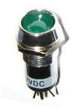
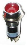
Before we can install the .dll software, we need to build 3 LED Lightning Asemblies and the Toggle Switch. The 2650 requires 6 LED Indicator Lights; 3 GREEN and 3 RED. Just what the panels look like, is up to you. You might consider Square, Retangular or Round. It's up to you. The only important consideration is the voltage rating. The 2650 supplied a +5VDC from the USB Port to the 6 Gear Status Lights. So these lights need to be about 5 to 12 volts. That is the only requirement. Below, is a schematic of one of the assemblies. Each assembly has 1 GREEN and 3 RED LEDs. If you purchased the 12 inch Extension Cables (Available on our PARTS Page), just solder the WHITE wire from the cable and solder it to the (+) side of the GREEN Light; solder the BLACK Wire to the (+) side of the RED Light. The remailing terminals on the LEDs (-) are soldered together and the RED Extension wire is soldered to either one of the common (-) LED terminal. You need to build 2 more assemblies just like this one.


White Wire
Black Wire
Red
Wire
Wire
3-Pin Extension Cable (12inch - cut to desired length)
6 to 12V LED Indicator Light
One GREEN
One RED
3 Assemblies Required
1 - LEFT Gear
1 - NOSE Gear
1 - RIGHT Gear
1 - LEFT Gear
1 - NOSE Gear
1 - RIGHT Gear
Landing Gear Light Assembly
+
+
-
IMPORTANT!
The LED Indicator Lights are a Polarity Sensitive Device. NOTE: that the (+) side of the LED is connected to the WHITE and BLACK wire of the Extension Cable.
The remaining 2 Terminals are connected together and soldered to the RED Extension Cable wire.
The LED Indicator Lights are a Polarity Sensitive Device. NOTE: that the (+) side of the LED is connected to the WHITE and BLACK wire of the Extension Cable.
The remaining 2 Terminals are connected together and soldered to the RED Extension Cable wire.
If you did not purchase the Extension Cables, ordinary #28 Stranded wire can be used instead. With the purchase of the 2650, we also included Four 3-pin Female connectors. Just solder the LEDs to these connectors using the Stranded Wire.
3-Pin Extension Cable
12 inch Cables are available
on our PARTS Page.
Before soldering to LED Indicator, the Larger of the 2 Extension Cable connectors needs to be cut off. The smaller of the 2 remains untouched. This is the side that will be plugged into the 2650 Board.
on our PARTS Page.
Before soldering to LED Indicator, the Larger of the 2 Extension Cable connectors needs to be cut off. The smaller of the 2 remains untouched. This is the side that will be plugged into the 2650 Board.
Cut this side Off

Toggle Switch Wiring
The next asembly is the Toggle Switch that is used to Raise and Lower the Landing Gear. For a simple but operational Landing Gear Lever, a standard Toggle Switch can be used. This switch can be either a SPDT (Single-Pole-Double Throw) or a DPDT (Double-Pole-Double-Throw). Below is a schematic showing how to wire the switch. Again, if you purchased the 3-pin Extension Cable, just follow the wire color. If not, you can use the #24 Stranded wire instead.


BOTTOM
Top
Center
Bottom
NOTCH on Neck of Switch

Landing Gear Lever Switch

White Wire
Black Wire
Red Wire

3-Pin Extension Cable
Landing Gear Lever - SPDT or DPDT may be used. Or design and build your own Lever Switch for a truly Reaslistic Panel
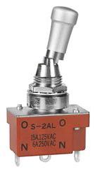
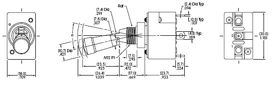
NKK Switch #S2AL can also be used
NKK Switch #S2AL can also be used
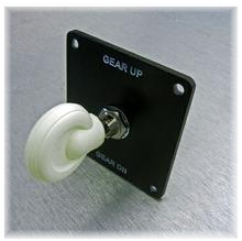
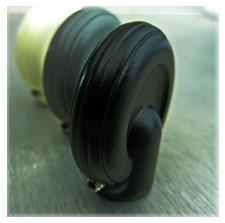
Whats nice about the 2650, you can make the panel as simple as you want or as elaborate as your pocketbook will allow. Below are 2 Landing Gear Levers I found on the internet just by using Google or BING search engines. Just look for Landing Gear Handles. You will be surprised just how many you can find. Below are just 2 of the many I found:
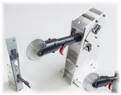
The only requirement is that thses handles MUST have some sort of switch (probably a Micro-switch) incorporated inside them. One set of contacts must close indicating that the lever is in the UP position and a second set of closing contacts indicating the DOWN Position.
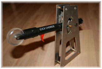
For a setup; not to inexpensive or not to pricy, you can use a military style SPDT Toggle switch with a LOCKING handle. The locking handle comes close to the lever used with a Beechcraft aircraft. To lower the Landing Gear, you need to pull on the handle while forcing it to the DOWN position. For Landing Gear retraction, just pull on the handle and force it in the UP position.
A recommend switch for this application, is the NKK S2AL Toggle. A GOOGLE search can direct you to a sales location.
NKK Switches S2AL SPDT
Locking Toggle Switch - PULL Handle OUT to unlock, then flip UP or DOWN
Locking Toggle Switch - PULL Handle OUT to unlock, then flip UP or DOWN
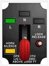
With all the sub-assemblies wired and ready to be installed inside your panel, now is a good time to consider just what the Landing Gear will look like. To the left is a recommended layout. It's a clean design and uses all available support of the 2650 boards. Note that there are just 3 LED Lights. You might consider using BI-Colored LED lights. When wired correctly, these lights will change from GREEN to RED or RED to GREEN depending on the location of the gears. Both colors are incorporated inside the same LED.
Putting it All Together
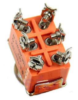
A 3-pin Male Connector.
The Toggle Switch is connected HERE
The Toggle Switch is connected HERE
The 3 LED Assembles are connected HERE (3x3 Male Connector
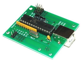
Putting all the components together is a Snap. The Toggle switch is connected to the 1x3 set of connectors on the left side of the board.
The 3 LED Asemblies are connected to the RIGHT side of the board (3x3 set of connectors) The proper orientation for each can be seen below.
The 3 LED Asemblies are connected to the RIGHT side of the board (3x3 set of connectors) The proper orientation for each can be seen below.


BOTTOM
Top
Center
Bottom
NOTCH on Neck of Switch


White Wire
Black Wire
Red Wire


To Connector 4 - To Connector 3


White Wire
Black Wire
Red
Wire
Wire
One GREEN
One RED
+
+
-
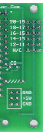


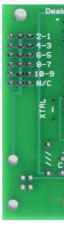
Pins 18 - 17 GREEN Right/RED Right
Pins 16 - 15 GREEN Left/RED Left
Pins 14 - 13 Green NOSE/RED NOSE
Pins 16 - 15 GREEN Left/RED Left
Pins 14 - 13 Green NOSE/RED NOSE


Connect the 3 LED Assemblies HERE

Connect this side of the connector to pins 18 for RIGHT Gear
Conect this side of connector to pin 16 for LEFT Gear
Conect this side of connector to pin 14 for Nose Gear
Conect this side of connector to pin 16 for LEFT Gear
Conect this side of connector to pin 14 for Nose Gear
0

2650 Board LEFT Side
2650 Board RIGHT Side
0
0
Suggested Knobs for the Landing Gear Board