
Thank you for your purchase of our Models 2045 , 2125 , 2165
USB Interface Circuit Boards. These 3 Models use the same circuit board
but have different pre-programmed chips installed. So here, we will discuss the
wiring of either the Toggle Switches or Push Buttons. Installation for all 3 Models are the same so the precedure will be covered only once.
Have any comments or sugestions, please write us at:
Support@DesktopAviator.com
Desktop Aviator HOME Page
International Shipping Info
Wiring the 2045/2125/2165
USB Interface Boards
USB Interface Boards
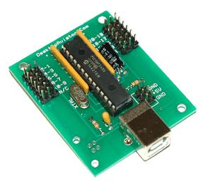
The Models 2045 , 2125 & 2165 all use the circuit board pictured here. The difference is the integrated circuit installed before shipping
The 2045 will create a constant Output; the 2125 will create Two 1/4 sec pulses at the same USB output, while the 2165 will create Two 1/4 sec pulses but at 2 different USB output locations

The Model 2045, 2125, 2165 (now to be called "The Boards" were designed to give the builder an easier way to connect the switches using a 3-pin extention cable. Just cut-off the "male" connector of the cable and solder the switches as seen below. Then just place the "female"side of the cable into any of the available J1 and J2 input pins. One 3-pin cable can be used to wire-up either ONE SPDT, TWO SPST
or TWO Spring Return PUSH BUTTONS. The Extension cables comes in 2 sizes; 12 inches and 20 inches. Both types have a Male and Female connector so by mating the M/F connectors together, you can easily lengthen the cables.
or TWO Spring Return PUSH BUTTONS. The Extension cables comes in 2 sizes; 12 inches and 20 inches. Both types have a Male and Female connector so by mating the M/F connectors together, you can easily lengthen the cables.
Board Layout
3-Pin Extension Cables
Also note that we also included a 2 x 3 connector that provides USB Power. This +5VDC can be used to power reed relays, LED indicator lights or any other small devices. Devices that draw a large amount of current can not be connected to the USB as it might cause harm to your computer's Power Supply.
Also note that the colors on the Extension Cable corresponds to the polarity of the 2 x 3 connector. The center wire on the Extension cable is red. So this indicates a (+) Positive polarity. The outter wire is colored BLACK which corresponts to GROUND. The WHITE wire is also connected to GROUND, so either Black or White wire is considered as GND.
Also note that the colors on the Extension Cable corresponds to the polarity of the 2 x 3 connector. The center wire on the Extension cable is red. So this indicates a (+) Positive polarity. The outter wire is colored BLACK which corresponts to GROUND. The WHITE wire is also connected to GROUND, so either Black or White wire is considered as GND.
Switch wiring for the 2125 Board
The 2125 Board creates 1/4 second Pulses at each of its 20 USB Outputs.
To take advantage of the 2125's configuration, you can wire 2 SPST Toggle switches as shown below. Here you have 1 terminal from each of the 2 toggle switches soldered together using standard stranded hookup wire. This is called the COMMON. The remaining terminals on the switches are soldered to the two outter wires on the 3-Pin Extension cable (These cables can be purchased from our PARTS Page). When complete, the cable can be connected to any of the available inputs on the 2125 board's input: 1-2, 3-4, 5-6, 7-8, 9-10, 11-12, 13-24, 15-16, 17-18 or 19-20. When connected to the USB Port on your computer (as seen on the Calibration Window), flip the two toggle switches; each will produce a 1/4 second pulse at the USB output corresponding to the input pine the switches were connected to. The USB output can be seen on the animation to the right.
To take advantage of the 2125's configuration, you can wire 2 SPST Toggle switches as shown below. Here you have 1 terminal from each of the 2 toggle switches soldered together using standard stranded hookup wire. This is called the COMMON. The remaining terminals on the switches are soldered to the two outter wires on the 3-Pin Extension cable (These cables can be purchased from our PARTS Page). When complete, the cable can be connected to any of the available inputs on the 2125 board's input: 1-2, 3-4, 5-6, 7-8, 9-10, 11-12, 13-24, 15-16, 17-18 or 19-20. When connected to the USB Port on your computer (as seen on the Calibration Window), flip the two toggle switches; each will produce a 1/4 second pulse at the USB output corresponding to the input pine the switches were connected to. The USB output can be seen on the animation to the right.
USB Output from the 2125 Board
Switch wiring for the 2165 Board
The 2165 Board creates ONE 1/4 second Pulse at each of its 20 USB Outputs. To take advantage of the 2165's configuration, you can wire 1 SPDT Toggle switch as shown below. Here you have the CENTER Terminal soldered to the center wire on the 3-pin Extension Cable or stranded hookup wire. This is called the COMMON. The 2 remaining terminals on the switch (the 2 remaining Terminals) are soldered to the two outter wires on the 3-Pin Extension cable. When complete, the cable can be connected to any of the available inputs on the 2237 board's input: 1-2, 3-4, 5-6, 7-8, 9-10, 11-12, 13-24, 15-16, 17-18 or 19-20. When connected to the USB Port on your computer (as seen on the Calibration Window), flip the toggle switch Up and then Down; each position will produce a 1/4 second pulse at the USB output corresponding to the input pins the switch was connected to. The USB output can be seen on the animation to the right.
USB Output from the 2165 Board
Switch wiring for the 2045 Board
USB Output from the 2045 Board
And finally, the 2045 Board. The 2045 creates a CONSTANT Ouput for as long as you keep pressing the push button down. The 2045 will product this constant ON output for all of its 20 inputs. To wire the 2045, you can wire 2 SPST Spring Return Push Button Switches as shown below. First, solder a jumper wire from either of the 2 terminals found on the push button switch. Then solder this COMMON connection point to the center wire on the 3-pin Extension Cable or stranded hookup wire. The 2 remaining terminals located on the push button are soldered to the two outter wires on the 3-Pin Extension cable. When complete, the cable can be connected to any of the available inputs on the 2045 board's input: 1-2, 3-4, 5-6, 7-8, 9-10, 11-12, 13-24, 15-16, 17-18 or 19-20. When connected to the USB Port on your computer (as seen on the Calibration Window), press either of the two buttons, the 2045 will create a constant ON condition on the USB Port for as long as you keep the button pressed. As before, the USB output seen on the Calibration window will light. These lights corresponds to the input pins the button were connected to. The USB output can be seen on the animation to the right.
Below is the layout for each of the 3 boards (less any components for clearity), unlike our Model 2040 (and equivalents) that has a J1 and J2 connector configured as a 17 x 2 input, "The Boards" have Two 3 x 6 input pins for both J1 and J2 inputs. This allows each 1 x 3 inputs to have TWO switches connected using just 1 Extension Cable. Each of the Boards support up to 20 switches, so as you can see the last of the 3 x 6 row of pins for both J1 and J2 are open pins so no connections can be made here (N/C see below). The CENTER Row of the J1 and J2 are the COMMON connections for ALL switches connected. Whereas the pins to the left and right of center are the CONTROL Inputs to the board.