

Thank you for your purchase of our Model 2670 Garmin 430 GNS Switch Panel designed exclusively for X-Plane v10/xx Flight Simulators.
Using the Easy Programming Instructions seen below, you can have your 2670 Panel up and running in minutes.
Now Enjoy your Newly Found X-Plane Realism!
Using the Easy Programming Instructions seen below, you can have your 2670 Panel up and running in minutes.
Now Enjoy your Newly Found X-Plane Realism!

Links to aviation directory
resources & information websites


Desktop Aviator HOME Page
International Shipping Info
Programming the
2670 X-Plane GNS Panel
2670 X-Plane GNS Panel

The Model 2670 GNS Panel was designed to be flush mounted inside your homemade aircraft panel or the GoFlight Panel Rack. The 2670 measures 7.25in inches by 4.0 inches.
Two mounting holes are provided to help in the fastening the Landing Gear Panel to your flightdeck or Rack.
Once mounted inside your flightdeck or GoFlight Rack, take the USB cable coming from the 2670 and insert it into an unused USB port on your computer. The computer will automatically sense and load the appropriate driver software. Once loaded, this software will remain on the computer even in the event of a power-down.
Installing the 420 GNS Panel
With the GNS Panel plugged into your computer and the driver software is loaded, it's now time to program the buttons and switches to perform the functions needed to execute all the requirements of the X-Plane' 430 GNS Panel.
Now would be a good time to let you know that you MUST Keep the Panel connected to the SAME USB port as it is now. If removed and placed into another USB port, all your programming will be lost. So before starting the programming, make sure you are comfortable with the 2670's USB port. If so, lets start programming the Panel.
Now would be a good time to let you know that you MUST Keep the Panel connected to the SAME USB port as it is now. If removed and placed into another USB port, all your programming will be lost. So before starting the programming, make sure you are comfortable with the 2670's USB port. If so, lets start programming the Panel.
Programming the 430 GNS Panel with X-Plane

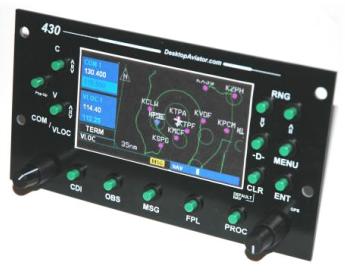
Below is a photo of the 2670 Panel showing all the Buttons and switches; all of which are assigned a number (In RED) corresponding to the Configuration Table further below

C
V
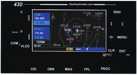

1

2


3
4


5
6


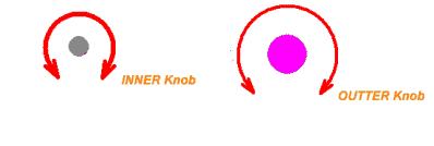
Dual Encoder
Switch Right
Switch Right
Dual Encoder
Switch Left
Switch Left
7
8
Dual Encoder Switch #1
Dual Encoder Switch #2
Encoder Push Button - Left Side - 23
Encoder Push Button - Right Side - 24


9
10
11
12
13
14
15
16
17
18
19
20
21
22
Unlike our Popular 2420 and the 2450 GPS Panels that uses one Dual Rotary Encoder Switch; the 2670 uses Two Dual Rotary Encoder Switches. One to Adjust NAV/COM Radio Frequencies and the second to set GPS functions.
Installation Instructions
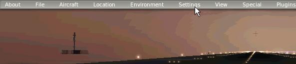
With X-Plane loaded and Running; use your Mouse to drag the cursor to the upper most edge of the computer screen. When there, you will see a listing of Options that can be opened. Drag the Cursor to "Settings" and "Click"
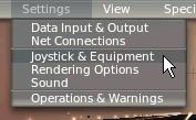
When "clicked"; a secondary screen will open showing you additional options. At this time, we are interested in "Joystick & Equipment". Highlight and click on this option.
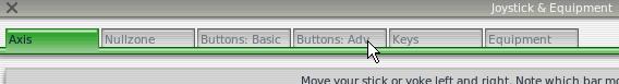

Now, Click on "Buttons: Adv". . .
. . .Now displayed is a large grid pattern with many flight function folders. At this time, we are only interested in the GPS/ folder. When highlighted, you will see a number of functions pertaining to the G-430 GNS panel. It is here where all of the 2670 settings will be made
NOTE: When a button is pressed or a Rotary Encoder is turned, a "check mark" will be displayed in one of the boxes of the grid, indicating the acceptance of the 2670 input.
| Button #9 | RNG Zoom-in | G430 Nav-1 zoom-in |
| Button #10 | RNG Zoom-out | G430 Nav-1 zoom-out |
| Button #12 | MENU | Nav-1 menu |
| Button #11 | -D- Waypoint | Nav-1 direct |
| Button #14 | ENTER | G430 Nav-1 ent |
| Button #13 | CLR | G430 Nav-1 clr |
| Button #15 | PROC | G430 Nav-1 proc |
GREEN Push Buttons


Below is a Table of commands that the 2670 will be programmed to. All commands can be found inside the GPS/ folder as shown above. With the 2670 plugged-in, press the #9 GREEN button (RNG zoom in). A small arrow will then be displayed on the Grid. Then going to the GPS/ folder, look for
"G430 Nav-1 zoom-in" and "click" on the circle to the left of the command. When clicked, the #9 button is now configured as the Zoom-in button on the 2670 panel. Now do the same for the remaining buttons and Duel Rotary Encoder Switches.
"G430 Nav-1 zoom-in" and "click" on the circle to the left of the command. When clicked, the #9 button is now configured as the Zoom-in button on the 2670 panel. Now do the same for the remaining buttons and Duel Rotary Encoder Switches.
TABLE #1
| Button #16 | FPL | G430 Nav-1 fpl |
| Button #17 | MSG | G430 Nav-1 msg |
| Button #18 | OBS | G430 Nav-1 obs |
| Button #19 | CDI | G430 Nav-1 cdi |
| Button #22 | C toggle | G430 Nav-1 com_ff |
| Button #21 | V toggle | G430 Nav-1 nav_ff |
| Button #20 | GPS Pop-up | G430 Nav-1 toggle popup |
GREEN Push Buttons - con't


| Button #23 | Encoder Push Button | G430 Nav-1 nav_com_tog. |
| Button #8 Large Knob | Encoder Turn Left | G430 COM/NAV1 coarse dn |
| Button #7 Large Knob | Encoder Turn Right | G430 COM/NAV1 coarse up |
| Button #6 Small Knob | Encoder Turn Left | G430 COM/NAV1 fine down |
| Button #5 Small Knob | Encoder Turn Right | G430 COM/NAV1 fine up |
| Button #24 | Encoder Push Button | G430 Nav-1 Push Cursor |
| Button #4 Large Knob | Encoder Turn Left | G430 Nav-1 Chapter down |
| Button #3 Large Knob | Encoder Turn Right | G430 Nav-1 Chapter up |
| Button #2 Small Knob | Encoder Turn Left | G430 Nav-1 Page dn |
| Button #1 Small Knob | Encoder Turn Right | G430 Nav-1 Page up |
Dual Encoder Switch (Right Side of Panel)
Dual Encoder Switch (Left Side of Panel)
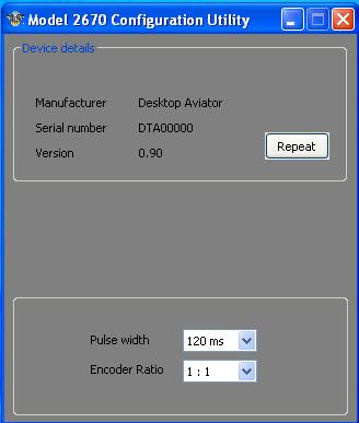
To the right shows a small program that allows you to change the Pulse Width and the encoder Ratio of the 2670 Panel. Factory default for these setings is: Pulse Width: 120ms / Encoder Ratio: 1:1. If needbe, you can change the Pulse width to increase or decrease the speed on which the computer can adjust the 2670's freq and GPS settings.
This Utility Can be downloaded HERE
This Utility Can be downloaded HERE
2670 Utility Software
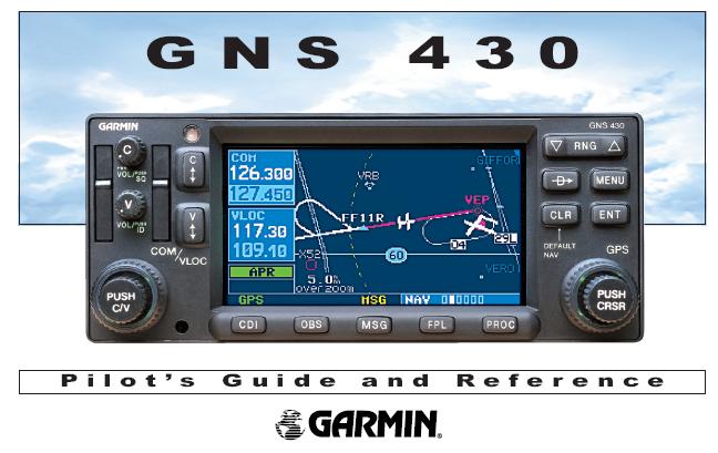
We also include a .pdf Instruction Booklet from Garmin, showing the ins-n-outs on the operation of the 430 GNS Panel.
You can download the Booklet HERE
You can download the Booklet HERE
Selected Garmin 430 tutorials from YouTube. Many more are available. Just do a YouTube Search "Garmin 430 Tutorial"
GARMIN 430 Video Instructions
Happy Flying!

Programming the 430 Panel with the help of XForcePC