


Desktop Aviator HOME Page
International Shipping Info


"Super Rotary Board
Model 2090
Wiring & Installation Instructions
Updated 08-26-2017
Wiring and Installing the
2090 Rotary Encoder
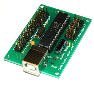
2090 Rotary Encoder
Installing the SUPER Encoder Board requires very little time. All you need is an unused USB Port. Additional Ports can be added to your computer by using a device called a USB Hub. These Hubs can be purchased for as little as $20.00 in the Internet.
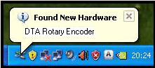
Just plug a USB Cable Series "B" into the jack on the 2090,
then into the USB Port on your computer. The computer will
sense the Adapter and load the required software for its proper
operation. The 2090 will be sensed as "DTA Rotary Encoder".
That s all there is to the installation.
To verify that you computer has accepted the Interface, you can goto the "Game Controller" window. To do this, just click on "START" (located in the lower left hand corner of the computer s monitor); then click on "Control Panel"; then "Game Controller". Your computer should display the following:
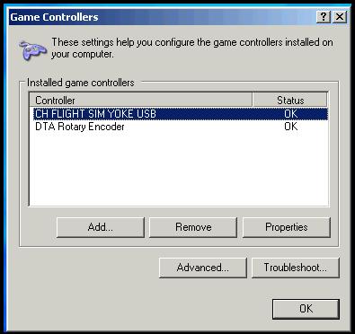
Highlight "DTA Rotary Encoder" then click "Properties"
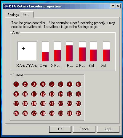
TABLE 1
The Properties Window indicates that there are are 32 available switch locations, this is a mis-conception. There are only 12 Buttons that can be used with your designs. The First 12 Digital Switches are RESERVED for use with the Rotary Switches.
Downloading the 2090 Utility Software
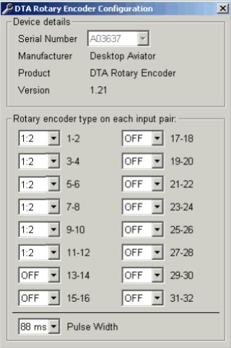
For the proper operation on the Encoder Board, you need to Download the Encoder Utility Program. This program allows you to adjust "Pulse Timing" and "Pluse Width" on each of the 6 Available Rotary Switches on the 2090 board. The program will also allow you to connect a number of Rotary Encoder Boards to the USB Port of same computer while allowing you to keep track on timing pusles on each and every Rotary Switch available on your system.
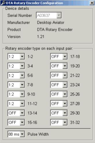
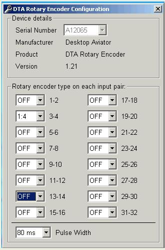
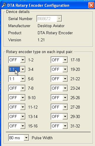
To the left is a photo of the Encoder Utility Program showing suggested settings for the first six Rotary Switches.
Please note that the Utility Program shows 16 available Rotary Switches, these aditional settings is for future expansion and is not available on the 2090 Board.
To Download this FREE program; click HERE. The number pair to the right of each setting shows the "Control Panel" RED dot that will be lite when the Rotary Switch is turned. Example: With the Rotary Switch connected to the 2090 Board at Position #1, turning the knob to the LEFT will light-up the #3 RED Button (quick pulse) as seen on the "Control Panel" window. Turn the Rotary Switch to the RIGHT, the #4 RED Button will light with a short pulse. If connected to Position #4, the
Turning the Rotary Dial to the LEFT then to the RIGHT will light (again a pulse) the RED #11 and then the RED #12. You get the idea.
On the top he Utility Program window, you will notice "Serial Number". Here you can set the timing and pulse duration for a number of 2090 Boards connected to your computer. This Serial Number will change when additional boards are added. Just select the Board you wish to program via its Serial Number, then set the timing pulse for the sugested 1:4 and Pulse width to 88 ms.
On the top he Utility Program window, you will notice "Serial Number". Here you can set the timing and pulse duration for a number of 2090 Boards connected to your computer. This Serial Number will change when additional boards are added. Just select the Board you wish to program via its Serial Number, then set the timing pulse for the sugested 1:4 and Pulse width to 88 ms.
Wiring Your Model 2090 Super Encoder Board
The 2090 was designed to provide three vital functions to any Flight Simmers Avionics Panel; they are Rotary Encoder Switches; Analog inputs from slide or rotary potentiometers and Digital inputs for 20 Push Buttons.
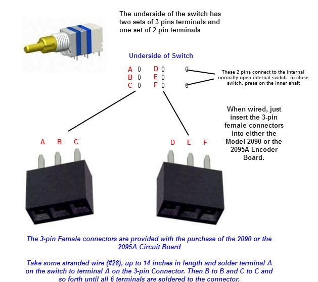
To make the interfacing of your Rotary Switches, Slide Controls and Push Buttons as painless as possible, we have included fourteen 3 Female Connectors. Just solder the wires (as shown below) from your switches to the connectors and place
them on the 2090.
To make the interfacing of your Rotary Switches, Slide Controls and Push Buttons as painless as possible, we have included fourteen 3 Female Connectors. Just solder the wires (as shown below) from your switches to the connectors and place
them on the 2090.
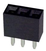
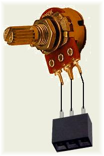
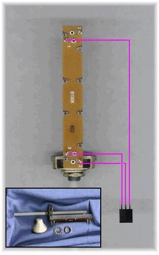
To connect the Rotary Switches to the 2090, all you need do it to solder 3 wires from the switch to one of the 3 pin female connectors provided with your purchase.
The length of these wires can be up to 15 inches long. Any longer, you run the risk of introducing noise into the board.
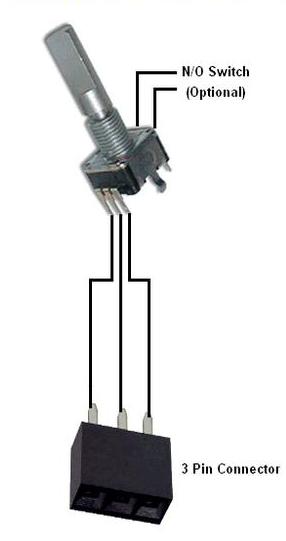
Using the schematic to the left, you can wire up to 6 Rotary Switches in this manner. The two additional terminals on the Rotary Switch are the contacts connected to a normally open spring return switch. These two contacts can be wired to the Digital Switch Matrix (see below) so when the Rotary Switch is PUSHED, the internal switch is closed for as long as you keep pressure on the shaft. This switch closure can then be programmed using FSUIPC to preform a needed function for your Avionics Panel.
Not all Rotary Switches come with a n/o switch but the switches we are making available to you have this unique feature.
The length of these wires can be up to 15 inches long. Any longer, you run the risk of introducing noise into the board.
Using the schematic to the left, you can wire up to 6 Rotary Switches in this manner. The two additional terminals on the Rotary Switch are the contacts connected to a normally open spring return switch. These two contacts can be wired to the Digital Switch Matrix (see below) so when the Rotary Switch is PUSHED, the internal switch is closed for as long as you keep pressure on the shaft. This switch closure can then be programmed using FSUIPC to preform a needed function for your Avionics Panel.
Not all Rotary Switches come with a n/o switch but the switches we are making available to you have this unique feature.
Wiring the Rotary Encoder Switches
Wiring LINEAR Potentiometers
The 2090 Board also supports up to 8 Analog inputs. These inputs can be programmed using your Flight Simulator s Settings Window. Along with the 6 standard LINEAR Inputs (Z Rotation, Dial, Slide ect), the board also supports X/Y inputs so as to allow you to build your own Flight Yoke.
It is recommend that the Value of the Rotary Potentiometer by about 100K Ohms; 10K ohms can also be used but the lower resistance value will allow for more current to be drawn from the computer s USB Port. REMEMBER! to use LINEAR Taper ONLY potentiometers.
To the left is the wiring what will be needed to install potentiometers to the board. The length of the wires can be about 12 to 18 inches. Any longer, shielded cable (microphone cable) wire is recommended.
With all needed potentiometers wired, remove the board from the computer s USB Port and insert the 3-pin connectors to the board. NOTE: the 3x8 male connector pine located to the right side of the board support theanalog input only.
When the potentiometers are connected to the board, reconnect the board to the computer's USB Port. Then using your computer, go into the Windoes Calibration Window. You will then see a BAR Graph for each of the potentiometer connected to the board. Using the Calibration function, each pot must be calibrated to allow the sensing of the full left/right turning of the pot's shaft. Instructions to calibrate the pots are given on each of the calibration windows.
When complete, you can now go into your flight sims SETTINGs Window, or FSUIPC and associate each potentiometer with the desired flight function.
When complete, you can now go into your flight sims SETTINGs Window, or FSUIPC and associate each potentiometer with the desired flight function.
Wiring SLIDE Potentiometers
As with Rotary Potentiometers, the 2090 also supports SLIDE Pots. Should you wish to make your own Push/Pull Throttle quadrant, slide pots are a must.
As with the rotary pots, Slide Potentiometers also come is two types; ANALOG and LINEAR. You should purchase LINEAR pots ONLY. Desktop Aviator has 100K Ohm Linear Slide Potentiometers on their PARTS Page.
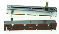
Wiring a slide is pretty much the same as the rotary but you need to pay attention to the 3 solder lugs located on the bottom. To the left is a photo that shows the needed wiring from the slide pot to the 3-pin female connector. The Wiper Arm Terminal is soldered to the center terminal of the 3 pin connector. The remaining 2 terminals on the pot are soldered to either end of the 3-pin connector. As with the rotary pot, the length of the wired can be about 12 to 18 inches in lenght (the shorter the better). Anything longer, shielded wire is recommended. When complete, remove the 2095A board from the USB Port. Connect the slide to any of the ANALOG Input terminals on the right side of the board; then reconect. Just like the rotary pot, the Slide Potentiometer will appear in the Calibration Window. Calibration of the Slide can then take place. When calibrated, the slide can then be programmed to controll the appropriate flight function.
As with the rotary pots, Slide Potentiometers also come is two types; ANALOG and LINEAR. You should purchase LINEAR pots ONLY. Desktop Aviator has 100K Ohm Linear Slide Potentiometers on their PARTS Page.
Wiring a slide is pretty much the same as the rotary but you need to pay attention to the 3 solder lugs located on the bottom. To the left is a photo that shows the needed wiring from the slide pot to the 3-pin female connector. The Wiper Arm Terminal is soldered to the center terminal of the 3 pin connector. The remaining 2 terminals on the pot are soldered to either end of the 3-pin connector. As with the rotary pot, the length of the wired can be about 12 to 18 inches in lenght (the shorter the better). Anything longer, shielded wire is recommended. When complete, remove the 2095A board from the USB Port. Connect the slide to any of the ANALOG Input terminals on the right side of the board; then reconect. Just like the rotary pot, the Slide Potentiometer will appear in the Calibration Window. Calibration of the Slide can then take place. When calibrated, the slide can then be programmed to controll the appropriate flight function.
Please NOTE: For any Analog Input Bar to appear in the Calibration Window for the 2090, you MUST have at least one potentiometer connected to the 2090 before plugging the board into your computer s USB Port. When connected, you would need to calibrate the 2090 as per the instructions shown in the Calibration Window.
Switch Assignments for the Model 2090
For the "Simplified" installation, you can take up to 6 Rotary Encoders; (wired as shown above). Connect them to the 2090 board using the 3 pin male connectors. The 2090 also supports Push Button Switch inputs for all unused Encoder switch inputs, but the internal software on the 2090 must be modified to tell the board where the push button switches are located. This can be done using the 2090 Utility Software as seen above.
On the left side of the board, you see Six 3x6 Male Header Pins (Rotary), Each of the 3 pins is is assigned
"Rotary encoder type on each input pair:". The default settings are seen to the below. 1-2, 3-4, 5-6, 7-8, 9-10, 11-12. These numbers correspond to the paired inputs on the 2090 board
On the left side of the board, you see Six 3x6 Male Header Pins (Rotary), Each of the 3 pins is is assigned
"Rotary encoder type on each input pair:". The default settings are seen to the below. 1-2, 3-4, 5-6, 7-8, 9-10, 11-12. These numbers correspond to the paired inputs on the 2090 board

Looking at the board, you see on the left side the 3x6 male header pins marked ROTARY. The upper most pair is position #1; then position #2 and so on. By connecting an encoder swith to Position #1, the Utility has control of this position on Input Pair 3-4. If an encoder switch were placed at Position #2, the Utility Software has control of that position at Input Pair 5-6 and so on.
This correlation can be seen on the table (below).
With the Utility Software set as seen to the left and all 6 encoder switches are connected, you have a standard setup. The turning of each encoder switch can be seen as pulses when viewed on the Calibration Window (Windows OS). The RED Buttons associated with the encoder switch turned, will flash for about 1/4 second.
The 2090 board also supports a variety of Encoder Switches. By clicking on the Down Arrow associated with the encoder you wish to change, you will have displayed a small window as seen here:
By selecting 1:1 - 1:2 - or 1:4, you are able top select the best encoder output for the switch being used at that location. Just click on any setting and the Utility Software will set and bring you back to the main screen.
The width of the output Pulse can also be set by Clicking on Pulse Width, then selecting the best time in msec.
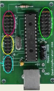
A Look at the 2090 Board
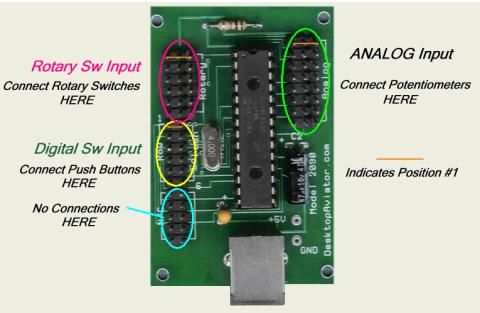
The "RED" oval shows where the 6 Rotary Switches can to be placed. Note the 3 Male Connectors in each row (left to right). This is where you will place the 3 terminal Female Connector. The one you just soldered the wires to.
The "Yellow" oval (no longer supported on the 2090 board) shows an expanded ROW/COLUMN pins where additional encoder switches can be wired. If more then 6 encoder inputs are needed, a much simplier way is to purchase the Model 2095A Board. The needed X/Y matrix is already incorporated on the 2095A Board with all the needed diodes.
The "GREEN" oval shows where you will insert the 3 pin connectors soldered to your Potentiometers. As with the Rotary Switchs, the Potentiometers are inserted horizontally.
The "BLUE" circle shows 5 pair of male connectors. At the present time, these terminals are not used. They are for future expansion.
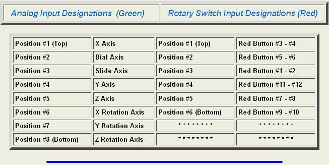
Lets start with the Analog Input TABLE. When the 2090 is connected to your computer and viewed on the "Control Panel" , you will see the window shown above (See Table 1). From this Table, you can see that the 8 Analog Inputs have names. X/Y, Z Axis, Y Rotation ect.
The X/Y Axis is usually associated with adding a Joystick. Joysticks can be purchased over the Internet for a few dollars and this is where it is connected to the 2090 Board (X Axis - Position #1 & Y Axis - Position #4). But you may ask; Where is Position #1? From the photo seen above; the #1 Positions for the three functions is indicated by the "Orange" horizontal Bar.
Say you want to use the "Y Rotation Axis" for one of your Slide Assemblies (any position can be used). Just place the 3 terminal connector (horizontally) into Position #7. Fuel Mix can be connected to Position #8 (Z Rotation Axis) and so on.
Rotary Switches are installed the same as the Analog Inputs. Again, refer to TABLE 1. This time focus your attention on the 32 RED Buttons. These Buttons indicate the available 32 Digital Switches of the MATRIX. The first 12 buttons are used for the Rotary Switches and/or Push Button. Say you place the 3 terminal connector from one of your Rotary Switches and place it Horizontally into Position #1 (Rotary Input Side "RED Circle"). When connected to your computer's USB Port and the computer showing the the Control Panel (As seen in TABLE 1), turn the Rotary Switch to the left and then the right. The RED Buttons #3 and #4 will begin to flash as you turn the switch. Now place a Rotary Switch into Position #4. When turned, left then right, the RED Buttons #11 and #12 will flash. If you see erratic behaviour when turning the Switch make sure you have the Rotary Switch UTILITY Programming running and properly set for the 6 Rotary Switches (see above)
The "Yellow" oval (no longer supported on the 2090 board) shows an expanded ROW/COLUMN pins where additional encoder switches can be wired. If more then 6 encoder inputs are needed, a much simplier way is to purchase the Model 2095A Board. The needed X/Y matrix is already incorporated on the 2095A Board with all the needed diodes.
The "GREEN" oval shows where you will insert the 3 pin connectors soldered to your Potentiometers. As with the Rotary Switchs, the Potentiometers are inserted horizontally.
The "BLUE" circle shows 5 pair of male connectors. At the present time, these terminals are not used. They are for future expansion.
Lets start with the Analog Input TABLE. When the 2090 is connected to your computer and viewed on the "Control Panel" , you will see the window shown above (See Table 1). From this Table, you can see that the 8 Analog Inputs have names. X/Y, Z Axis, Y Rotation ect.
The X/Y Axis is usually associated with adding a Joystick. Joysticks can be purchased over the Internet for a few dollars and this is where it is connected to the 2090 Board (X Axis - Position #1 & Y Axis - Position #4). But you may ask; Where is Position #1? From the photo seen above; the #1 Positions for the three functions is indicated by the "Orange" horizontal Bar.
Say you want to use the "Y Rotation Axis" for one of your Slide Assemblies (any position can be used). Just place the 3 terminal connector (horizontally) into Position #7. Fuel Mix can be connected to Position #8 (Z Rotation Axis) and so on.
Rotary Switches are installed the same as the Analog Inputs. Again, refer to TABLE 1. This time focus your attention on the 32 RED Buttons. These Buttons indicate the available 32 Digital Switches of the MATRIX. The first 12 buttons are used for the Rotary Switches and/or Push Button. Say you place the 3 terminal connector from one of your Rotary Switches and place it Horizontally into Position #1 (Rotary Input Side "RED Circle"). When connected to your computer's USB Port and the computer showing the the Control Panel (As seen in TABLE 1), turn the Rotary Switch to the left and then the right. The RED Buttons #3 and #4 will begin to flash as you turn the switch. Now place a Rotary Switch into Position #4. When turned, left then right, the RED Buttons #11 and #12 will flash. If you see erratic behaviour when turning the Switch make sure you have the Rotary Switch UTILITY Programming running and properly set for the 6 Rotary Switches (see above)
Installing Spring Return Push Buttons
If you are not using the 2090 board to its full capacity of 6 encoder switches, the unused inputs can be reconfigured to support 2 push button switches. To the right is a typical wiring arrangement for the switches. Any type of switch or design can be used with the board.
With the 3-pin connectors supplied with your purchase, wire the switches as seen.
These two switches take the place of one rotary encoder switch, so wire-up 4 more assemblies as this. You will now have 10 push buttons (5 assemblies).
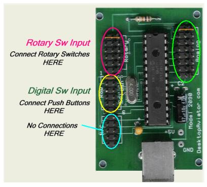
Below is a photo of the 2090 board. At this time, we are interested in the RED Oval (Rotary Sw Input). Take the 3-pin connector soldered to the Rotary encoder Switch and place in on the first row of male terminals of the RED Oval (Orange line).
Now, take the 5 push button assemblies and place the 3-pin connectors from each assembly, and insert them into the remaining Rotary Sw Input (RED Oval).
The wiring in now complete. All we need do now is to program the board using the 2090 Utility Program.
With the 3-pin connectors supplied with your purchase, wire the switches as seen.
These two switches take the place of one rotary encoder switch, so wire-up 4 more assemblies as this. You will now have 10 push buttons (5 assemblies).
Below is a photo of the 2090 board. At this time, we are interested in the RED Oval (Rotary Sw Input). Take the 3-pin connector soldered to the Rotary encoder Switch and place in on the first row of male terminals of the RED Oval (Orange line).
Now, take the 5 push button assemblies and place the 3-pin connectors from each assembly, and insert them into the remaining Rotary Sw Input (RED Oval).
The wiring in now complete. All we need do now is to program the board using the 2090 Utility Program.
Connect the 2090 board to your computer's USB Port. The computer will sense and load the required Driving Software. Now; click on the icon of the 2090 Utility Program. A window will open on the screen. For the proper operation of the newly 10 push button switches and the Rotary encoder, you would need to "SET" the Utility Program to work with the switches. Using your computer's mouse, "SET" the "3-4" window to "1:4". All others will remain "OFF".
Now goto the Calibration Window and press each switch. You will now get a Constant ON output indicated by the lighting of the corresponding RED Button. Then program the button as needed with your Flight Sim software.
Now goto the Calibration Window and press each switch. You will now get a Constant ON output indicated by the lighting of the corresponding RED Button. Then program the button as needed with your Flight Sim software.
The Utility Software also allows you to select the best suited Pulse Width for your application.
With the Utility Program running; notice the small window marked "Pulse Width". By clicking on the Down Arrow icon, you are able to set the width from about 50msec to 130msec, Just highlight the time that best suits the needs of your Flight Sim software. When selected, you will be brought back to the main screen. We find that a Pulse width from 70msec to 80msec is the best choice for most applications.
Obviously, the Pulse Width will only be effecting when Rotary Encoder switches are connected to the board. It has no effect when using Push Buttons or Toggle switches (SPDT / DPDT).
Installing an Optical Rotary Encoder Switch
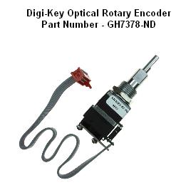
I had a few request on how to install an Optical Rotary Encoder Swith to the 2090 board. Although the Optical Switch does require a few additional outboard resistors, it can be done quite easily. For this demo wiring I be using a GH7378-ND from Digi-Key seen to the left.
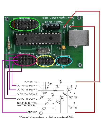
As you can see from the schematic, the Optical Rotary Encoder has 4 transistors and 4 internal LEDs; all of which must be powered for operation. The 5 Volts need for the switch can be gotten from the 2090 board at its 5VDC and GDN pads. Just take 2 wires and solder the + and GND from the 2090 to the connector block on the Rotary Encoder Switch.
From either side (the 2090 or the optical switch), you must connect four 2.2K ohm resistors (1/4W or 1/8W) as shown.
The other 5 wires are connected to the Rotary Input (RED Oval) of the 2090 as shown. Seeing that the center terminal of the 2090 Rotary input is a common ground, only one wire is needed at this point. The other 4 wires connect the A and B Optical Rotary Encoder switch to the 2090.
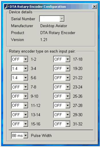
With the wiring complete, run the 2090 Utility Software. Plug the 2090 board into an unused USB Port of your computer. Your Utility Program will show the panel seen to the left. Now "Set" the 3-4 rotary pair to 1:4 and the 5-6 pair to 1:4. Pulse Width to 88ms.
To test the 2090 board, go into the Calibration window and turn the Rotary Switch to the left then to the right. The #3 - #4 and the #5 - #6 "RED Buttons" will flash. Now, all you need do is to use your Flight Simulator program and set these "buttons" to the desired Flight Functions. A NAV/COM radio frequency adjustment feature should be a good starting point to experiment with your new board.
To test the 2090 board, go into the Calibration window and turn the Rotary Switch to the left then to the right. The #3 - #4 and the #5 - #6 "RED Buttons" will flash. Now, all you need do is to use your Flight Simulator program and set these "buttons" to the desired Flight Functions. A NAV/COM radio frequency adjustment feature should be a good starting point to experiment with your new board.
For additional Information on wiring, programming and installing Toggle switches, please goto:
http://www.desktopaviator.com/Instructions/Model_2095A/index.htm
The 2090 and the 2095A Boards use the same chip so programming and wiring are simlilar
http://www.desktopaviator.com/Instructions/Model_2095A/index.htm
The 2090 and the 2095A Boards use the same chip so programming and wiring are simlilar
Setting the Pulse width
Addium 8-26-2017
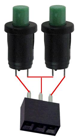
A few months back, we started offering a small and very inexpensive Dual Rotary Encoder Switch with mounting circuit board and knobs. It can be seen on our PARTS Page. With some basic wiring skills, you can easily connect the encoder switch to either the 2090 or the 2095A Boards.
So this is how it is done. . . . .
So this is how it is done. . . . .
GREEN Oval - DO NOT connect any encoder switches here!Potentiometers ONLY. You will damage your encoder switch

YELLOW/BLUE Oval - No Longer Supported!


Configuring the 2090 board to accept the Dual Encoder Switch
To the Left is the 2090 Utility Software that allows you to re-configure the board to accept the Dual rotary encoder Switch. It can be downloaded HERE
As seen above, we need to change the Rotary Encoder Input Pair from 1:2 to 1:1 for the location you connect the encoder switch on the board.
As seen above, we need to change the Rotary Encoder Input Pair from 1:2 to 1:1 for the location you connect the encoder switch on the board.
Take a look at the 2090 board (upper right) and notice the Orange horizontal line located inside the RED Oval. From what was discussed above, each pair of encoder inputs are numbered 1-2, 3-4, 5-6 all the way to 31-32. Seeing that the 2090 supports 6 encoder inputs numbered 1-2 to 11-12 are used the rest are ignored.
With your Encoder Switch wired as indicated above, insert the 3-pin female connector to the first horizontal row inside the RED Oval (look for the Orange Bar). This input is labeled 3-4. The next row down is labeled 5-6.
Now, with the encoder connected, plug the board into an unused USB Port on your computer, With the 2090 Utility Software downloaded and running, click on the down arrow button for the small windoe labeled 3-4. You will then see a dropdown menu; click on 1:1. Do the same for the small window labeled 5-6. That's it! You jusr configured the 2090 board to support the Dual Rotary Encoder Switch.
To test your siring, go into the Calibration Window; look for DTA Rotary Encoder, then click.
Rotate the encoder switch to the left, then to the right; you will then see the small RED buttons (3-4 and 5-6) flash.
You can now configure the 2090 board to adjust flight functions using FSX/FSUIPC, P3D and X-Plane flight sims.
Should you wish to make use of the encoder's internal normally open push switch, solder 2 wires from the center terminal of the 3-pin female connector, one wire soldered to the CENTER Terminal and the second wire to either left or right terminal and the 2 remaining terminals on the encoder switch.
Place the 3-pin Connector to the third row down on the 2090 board. This location is labeled 1-2.
Note that location 1-2 is in the OFF position. This is needed for the 2090 to "see" this location as a button input rather an encoder input.
When pressed, the #1 RED button in the Calibration Window will light until you remove your finger from the switch.
Connect All Rotary Encoder Switches HERE

ORANGE Line - First Row
