

Desktop Aviator HOME Page
International Shipping Info

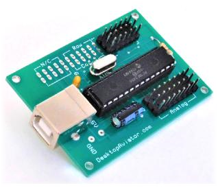
"D/A Interface Board
Model 2770
Wiring & Installation Instructions
Wiring and Installing the
2770 Digital/Analog Interface
2770 Digital/Analog Interface
Installing the D/A Interface requires very little time. All you need is an unused USB Port. Additional Ports can be added to your computer by using a device called a USB Hub. These Hubs can be purchased for as little as $20.00 in the Internet.
Just plug a USB Cable Series "B" into the jack on the 2770, then into the USB Port on your omputer. The computer will sense the Adapter and load the required software for its proper operation. The 2770 will be sensed as "D/A Interface".
To verify that you computer has accepted the Interface, you can goto the "Game Controller" window. To do this, just click on "START" (located in the lower left hand corner of the computer s monitor); then click on "Control Panel"; then "Game Controller".
The Properties Window indicates that there are are 32 available switch locations, this is a mis-conception. There are only 12 Buttons that can be used with your designs. The First 12 Digital Switches are RESERVED for use with the Spring Return Push Buttons or Toggle/Rocker Switches (SPDT type).

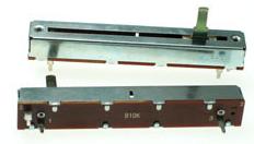
Wiring LINEAR Potentiometers
The 2770 Board also supports up to 8 Analog inputs. These inputs can be programmed using your Flight Simulator s Settings Window. Along with the 6 standard LINEAR Inputs (Z Rotation, Dial, Slide ect), the board also supports X/Y inputs so as to allow you to build your own Flight Yoke.
It is recommend that the Value of the Rotary Potentiometer by about 100K Ohms; 10K ohms can also be used but the lower resistance value will allow for more current to be drawn from the computer s USB Port. REMEMBER! to use LINEAR Taper ONLY potentiometers.
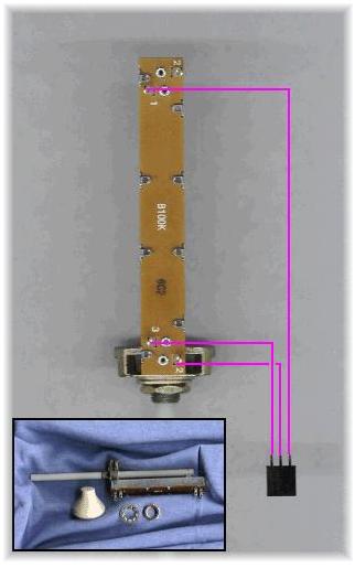
To the left is the wiring what will be needed to install potentiometers to the board. The length of the wires can be about 12 to 18 inches. Any longer, shielded cable (microphone cable) wire is recommended.
With all needed potentiometers wired, remove the board from the computer s USB Port and insert the -pin connectors to the board. NOTE: the 3x8 male connector pins located to the right side of the board support the analog input only.
It is recommend that the Value of the Rotary Potentiometer by about 100K Ohms; 10K ohms can also be used but the lower resistance value will allow for more current to be drawn from the computer s USB Port. REMEMBER! to use LINEAR Taper ONLY potentiometers.
To the left is the wiring what will be needed to install potentiometers to the board. The length of the wires can be about 12 to 18 inches. Any longer, shielded cable (microphone cable) wire is recommended.
With all needed potentiometers wired, remove the board from the computer s USB Port and insert the -pin connectors to the board. NOTE: the 3x8 male connector pins located to the right side of the board support the analog input only.
When the potentiometers are connected to the board, reconnect the board to the computer's USB Port. Then using your computer, go into the Calibration Window. You will then see a BAR Graph for each of the potentiometer connected to the board. Using the Calibration function, each pot must be calibrated to allow the sensing of the full left/right turning of the pot's shaft. Instructions to calibrate the pots are given on each of the calibration windows.
When complete, you can now go into your flight sims SETTINGs Window, or FSUIPC and associate each potentiometer with the desired flight function.
If you are using X-Plane 11, potentiometer calibration can now be accomplished in the program
itself under the SETTINGs window. Just follow the simple on-screen prompts.
Wiring SLIDE Potentiometers
As with Rotary Potentiometers, the 2770 also supports SLIDE Pots. Should you wish to make your own Push/Pull Throttle quadrant, slide pots are a must.
As with the rotary pots, Slide Potentiometers also come is two types; ANALOG and LINEAR. You should purchase LINEAR pots ONLY. Desktop Aviator has 100K Ohm Linear Slide Potentiometers on their PARTS Page.
Wiring a slide is pretty much the same as the rotary but you need to pay attention to the 3 solder lugs located on the bottom. To the left is a photo that shows the needed wiring from the slide pot to the 3-pin female connector. The Wiper Arm Terminal is soldered to the center terminal of the 3 pin connector. The remaining 2 terminals on the pot are soldered to either end of the 3-pin connector. As with the rotary pot, the length of the wired can be about 12 to 18 inches in lenght (the shorter the better). Anything longer, shielded wire is recommended. When complete, remove the 2770 board from the USB Port. Connect the slide to any of the ANALOG Input terminals on the right side of the board; then reconect. Just like the rotary pot, the Slide Potentiometer will appear in the Calibration Window. Calibration of the Slide can then take place. When calibrated, the slide can then be programmed to controll the appropriate flight function.
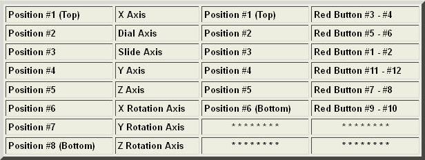
Lets take a look at the Table seen above; the Analog Input side. When the 2770 is connected to your computer and viewed on the "Control Panel" , you will see the window shown above (Table 1). From this Table, you can see that the 8 Analog Inputs have names. X/Y, Z Axis, Y Rotation ect.
The X/Y Axis is usually associated with adding a Joystick. Joysticks can be purchased over the Internet for a few dollars and this is where it is connected to the 2770 Board (X Axis - Position #1 & Y Axis - Position #4). But you may ask; Where is Position #1? From the photo seen above; the #1 Positions for the three functions is indicated by the "Orange" horizontal Bar.
Say you want to use the "Y Rotation Axis" for one of your Slide Assemblies (any position can be used). Just place the 3 terminal connector (horizontally) into Position #7. Fuel Mix can be connected to Position #8 (Z Rotation Axis) and so on.
Wiring Your 2770 D/A Interface Board
The 2770 was designed to provide two vital functions to any Flight Simmers Avionics Panel; they are Analog inputs from slide or rotary potentiometers and Digital inputs for 12 Push Buttons or 6 SPDT Toggle/Rocker Switches.
To make the interfacing of your Slide Controls and Switches as painless as possible, we have included fourteen 3 Female Connectors. Just solder the wires (as shown below) from your switches to the connectors and place
them on the 2770.
To make the interfacing of your Slide Controls and Switches as painless as possible, we have included fourteen 3 Female Connectors. Just solder the wires (as shown below) from your switches to the connectors and place
them on the 2770.
Please NOTE: For any Analog Input Bar to appear in the Calibration Window for the 2770, you MUST have at least one potentiometer connected to the 2770 before plugging the board into your computer s USB Port. When connected, you would need to calibrate the 2770 as per the instructions shown in the Calibration Window.
Installing Spring Return Push Buttons
The 3x6 male connector pins seen om the left side of the board support up to 12 Sprint Return Push Button switches or 6 SPDT Toggle or Rocker Switches.
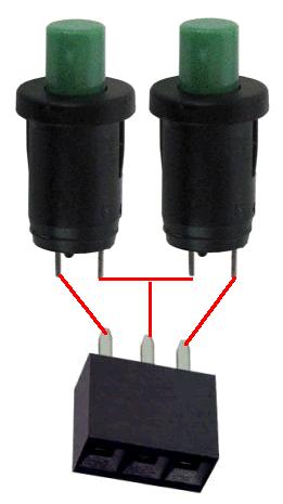
To the right is a typical wiring arrangement for the switches. Any type of switch or design can be used with the board.
With the 3-pin connectors supplied with your purchase, wire the switches as seen.
These two switches take the place of one toggle/rocker switch, so wire-up 5 more assemblies as this. You will now have 10 push buttons (6 assemblies).
Below is a photo of the 2770 board. At this time, we are interested in the RED Oval (Digital Input). Take the 3-pin connector soldered to the Button Asembly and place in on the first row of male terminals of the RED Oval (Orange line).
Now, take the 5 push button assemblies and place the 3-pin connectors from each assembly, and insert them into the remaining Rotary Sw Input (RED Oval).
The wiring in now complete. All we need do now is to program the board using the 2770 Utility Program.
You can now set the function for each button using FSX/FSUIPC or X-Plane's SETTINGs window.
ANALOG Input (Right Side of Board)
DIGITAL Input (Left Side of Board)
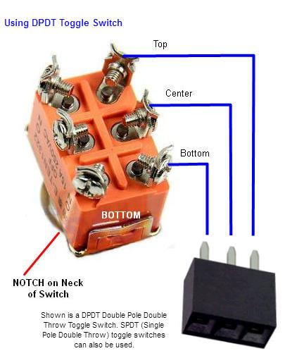

To the left is a DPDT (Double Pole Double Throw Toggle switch. Rocker Switches also come in this configuration.
Both Toggle and Rocker switches can be wired to the 2770 board using the 3-pin connectors that came with your purchase. Just follow the easy wiring as seen. Or if you prefer, 3-pin Extension Cables can be purchased from our PARTS page.
When wired, just insert the switch's connector to the 2770 board. When connected, you can now set each of the 6 toggle switches to the required flight function showing:
Landing Lights ON
Landing Lights OFF
Each function needs to have separate ON and OFF settings.
The 2770 Board
12 DIGITAL Inputs
Connect your Spring Return Push Buton Switches or 6 DPDT Toggle/Rocker Switches HERE
Connect your Spring Return Push Buton Switches or 6 DPDT Toggle/Rocker Switches HERE

8 Analog Inputs
Connect your Rotary or Slide otentiometers HERE
Connect your Rotary or Slide otentiometers HERE

If you wish, you can mix Push Button and Toggle Switches on the same board.


Orange Bar - indicates
this is the #3 - #4 Switch
Input
this is the #3 - #4 Switch
Input